

Construction projects across Delaware are scaling up rapidly. From multi-family commercial developments along the Wilmington waterfront to modern healthcare facilities in Dover and expanding industrial hubs in Sussex County, builders face aggressive schedules and tight margins. In this high-stakes environment, spatial errors are the biggest threat to profitability. When a 12-inch main supply duct collides with a structural steel beam, work halts instantly on site.
To eliminate these costly conflicts before breaking ground, leading general contractors, design-build firms, and MEP subcontractors rely on professional Revit MEP clash detection Delaware services. By combining the intelligent 3D modeling power of Autodesk Revit with the advanced spatial coordination engine of Navisworks, engineering teams can identify, report, and resolve multi-discipline clashes virtually.
This comprehensive guide explores how automated MEP clash detection Delaware workflows operate, why software integration matters for modern building projects, and how partnering with specialized BIM clash detection services ensures flawless execution from design through installation.
The True Cost of Unresolved MEP Clashes on Delaware Jobsites
Traditional 2D CAD workflows rely heavily on flat paper overlays. Design engineers attempt to spot visual overlaps across architectural, structural, and mechanical drawings. However, when complex trades converge in dense areas—such as plenum spaces, mechanical rooms, and vertical risers—2D overlays inevitably fail.
Unidentified spatial conflicts turn into direct jobsite errors during active construction. When field installers discover an obstacle on-site, the consequences ripple across the entire project ecosystem:
1. Costly Field Rework and Change Orders
When trades encounter spatial conflicts, pre-fabricated pipes or duct runs cannot be installed as designed. Field crews must stop work, issue a Request for Information (RFI), and wait for engineering re-routing approval. Modify-in-field adjustments lead to excessive labor expenses, wasted materials, and cumulative change orders that erode contract profit margins.
2. Schedule Delays and Trade Stacking
A single unresolved clash in a mechanical room can delay downstream trades for days or weeks. Drywall contractors, electricians, and ceiling installers are forced to stand by while engineers resolve routing issues. This causes trade stacking, overcrowding, safety risks, and potential liquidated damages for missed project milestones.
3. Compromised Building Maintenance Access
Even if a trade managed to install a pipe around a structural column without bumping into it, they might block access to critical valves, electrical panels, or damper actuators. Physical clearance issues severely impair long-term facility operations and lifecycle maintenance for building owners.
Through proactive Revit MEP coordination and virtual pre-construction, builders transform these expensive field emergencies into simple computer clicks during early design phases.
Revit vs. Navisworks: The Dynamic Duo of Modern MEP Coordination
Achieving a clash-free coordination model requires combining distinct software capabilities. While Autodesk Revit serves as the primary authoring platform for parametric building components, Autodesk Navisworks acts as the high-powered aggregation and analysis engine.
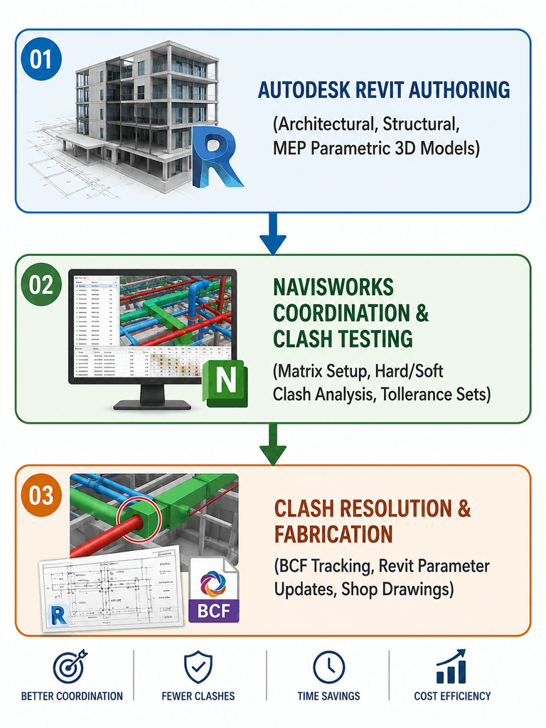
Autodesk Revit: Parametric Modeling and System Authoring
Revit allows engineers and trade designers to build rich 3D digital representations of mechanical, electrical, plumbing, and fire protection systems (MEPF). Every component—from a VAV box to an elbow fitting—contains accurate physical dimensions, elevation metrics, and system connectivity data.
- Parametric Adjustments: Modifying an elevation in Revit automatically updates connected fittings, schedules, and sections.
- Intelligent Clearance Zones: Designers can model clearance envelopes around equipment to reserve required space for maintenance and code compliance.
Autodesk Navisworks: Multi-Discipline Aggregation and Clash Matrix Analysis
While Revit performs basic native element checks, large-scale commercial models contain millions of objects across separate files. Loading architectural, structural, and MEP files directly into one workspace can slow standard hardware.
Autodesk Navisworks clash detection tools solve this by converting heavy authoring models into lightweight .NWD or .NWC formats. Navisworks executes high-speed spatial tests across millions of elements in seconds:
- Batch Testing: Running automated clash matrix tests between specific system layers (e.g., HVAC Supply Duct vs. Structural Framing).
- Tolerance Controls: Defining acceptable clear distances based on project phases, insulation thickness, and installation margins.
- Clash Grouping & Group Management: Consolidating hundreds of duplicate hits caused by a single continuous pipe into a single, manageable issue report.
Integrating these two software suites forms the backbone of modern BIM Modeling Services, bridging the gap between design intent and field constructability.
3 Core Types of Construction Clashes Resolved in BIM
Clash detection goes beyond preventing two solid objects from occupying the same space. Comprehensive visual coordination identifies three distinct conflict categories:
1. Hard Clashes (Physical Intersections)
A hard clash occurs when two distinct physical building components occupy identical 3D coordinates.
- Common Examples: A domestic water line penetrating a structural concrete beam, or main supply ductwork running directly through an elevator shaft.
- Resolution: Re-routing system paths in Revit or adjusting floor-to-floor heights early in design.
2. Soft Clashes (Clearance Encroachments)
A soft clash occurs when an object breaches the spatial buffer, insulation envelope, or operational clearance zone required around another component.
- Common Examples: High-voltage electrical conduit routed too close to hot water piping, or HVAC clashes where ductwork blocks access to an overhead air handler filter rack.
- Resolution: Applying dynamic tolerance rules in Navisworks to preserve maintenance corridors and satisfy local building codes.
3. Workflow & Temporal Clashes (4D Schedule Conflicts)
A workflow or 4D clash involves logistical and installation sequence errors over time.
- Common Examples: Installing sub-ceiling drywall before large mechanical chillers are lowered into position, or crane swing overlap during prefabricated structural assembly.
- Resolution: Integrating 3D geometry with 4D schedule data to simulate installation sequences virtually before mobilization.
Cross-Trade MEPF Coordination: Managing the Key Systems
Executing successful Revit MEP Clash Detection Delaware requires systematic coordination across all major building trades:
HVAC and Mechanical Systems
Ducted supply and return lines occupy the largest volume in ceiling plenums. Early clash resolution focuses on placing main duct runs first, establishing clear elevations, and preventing structural beam collisions before detailing secondary branches.
Plumbing and Drainage Systems
Unlike pressurized pipes, gravity-fed plumbing lines (sanitary waste and storm drains) require continuous, unyielding slope angles. During plumbing clashes analysis, plumbing routes are given priority because altering their pitch disrupts system functionality.
Electrical and Cable Trays
While flexible small-diameter electrical conduits can bend around obstacles on site, large busways, high-voltage conduits, and primary cable trays require dedicated raceways. Resolving electrical clashes in BIM prevents high-voltage interference and preserves ceiling access.
Fire Protection Piping
Fire sprinkler lines must comply strictly with structural clearances and local fire codes (such as NFPA standards). Resolving fire protection conflicts early ensures main lines, branch piping, and drop heads align seamlessly with ceiling grid layouts and lighting fixtures.
For a deeper dive into trade-specific modeling standards, review our specialized guides on MEP BIM Modeling to see how standardized 3D models streamline multi-trade integration.
Step-by-Step Workflow for Revit MEP Clash Detection in Delaware
To maximize efficiency, general contractors and engineering teams follow a structured, multi-stage coordination workflow:
Step 1: Model Standardization and Setup
Before running tests, all trade contractors must align project coordinates, datum levels, units of measure, and modeling tolerances in Autodesk Revit. Establishing shared coordinates prevents model misalignment when merging files.
Step 2: File Export and Model Aggregation
Each trade exports their native .RVT models into lightweight .NWC cache files. The BIM Manager imports these files into Navisworks Manage, combining architectural walls, structural framing, and MEP systems into a unified master coordination model.
Step 3: Setting the Clash Matrix and Running Tests
The BIM coordinator configures a systematic clash matrix. Instead of running a generic test that yields 10,000 irrelevant hits, tests are divided logically into system pairs:
- Structural Steel vs. Mechanical Supply Ducting
- Plumbing Waste Gravity Lines vs. Electrical Cable Trays
- Fire Sprinkler Branches vs. Architectural Ceiling Grids
Filtering out components smaller than a specific tolerance threshold (e.g., ignoring 1-inch conduits during initial rough-in checks) ensures teams focus on critical structural and spatial conflicts.
Step 4: Collaboration and BCF Issue Tracking
Once Navisworks generates conflict reports, identical clashes are grouped into single actionable items. Coordinators assign ownership to specific trades using standard BIM Collaboration Format (BCF) workflows or cloud-based platforms like Autodesk Construction Cloud / BIM 360. Each issue includes precise 3D camera viewpoints, grid locations, element IDs, and assigned resolution deadlines.
Step 5: Native Revit Updates and Verification
Trade designers open the assigned BCF issues directly inside Autodesk Revit using plugins like Revit Clash Communicator or Navisworks SwitchBack. Designers modify pipe slopes, shift duct runs, or lower ceiling heights in native authoring software. Updated models are re-exported to Navisworks to verify that clashes are successfully resolved without creating secondary conflicts.
Key Benefits for Delaware Subcontractors and Contractors
Implementing accurate Revit MEP clash detection Delaware workflows transforms jobsite performance across three key dimensions:
| Project Metric | Traditional 2D CAD Process | BIM-Driven Clash Detection | Business Impact |
| Field RFIs | 150 – 300+ per project | Reduced by 70% – 85% | Minimizes administrative delay and engineering backlog |
| Change Orders | 5% – 10% of total budget | Under 1% of total budget | Protects project profitability and contingency funds |
| Off-Site Fabrication | High risk of field modifications | Up to 95% constructible accuracy | Enables rapid modular assembly and off-site spooling |
| Construction Timeline | Frequent delays from trade conflict | On-time project delivery | Eliminates costly schedule slip and labor trade stacking |
To learn how virtual coordination integrates into full project management schedules, explore our detailed breakdown of BIM Coordination Services for multi-family, commercial, and industrial developments.
Building successful projects in Delaware requires strict adherence to national and regional building codes, design guidelines, and BIM execution standards. Integrating federal and institutional guidelines into your BIM coordination matrix ensures full compliance during regulatory reviews:
National Institute of Building Sciences (NIBS): Reference the official National BIM Standard – United States for established framework rules on data interoperability, level of development (LOD), and open BIM standards across architectural and engineering disciplines.
Partner with Acura BIM for Error-Free Construction in Delaware
Managing complex multi-discipline coordination in-house requires expensive software licensing, dedicated BIM hardware, and specialized staff. For many MEP subcontractors and general contractors across Delaware, outsourcing coordination to a trusted BIM engineering partner provides immediate access to expert modeling power without heavy overhead.
At Acura BIM, we specialize in high-precision 3D MEP modeling, clash identification, and comprehensive trade coordination. Our engineering team brings deep industry experience using Autodesk Revit, Navisworks Manage, and cloud-based BIM environments to deliver fully clash-free, constructible digital models.
Our Core MEP Coordination Services Include:
- Multi-Discipline Clash Matrix Setup & Testing: Running thorough hard and soft clash analysis across HVAC, plumbing, electrical, and structural systems.
- Constructability Reviews & RFI Reduction: Identifying design inconsistencies, clearance violations, and maintenance bottlenecks before drawings go to the field.
- Spool-Ready Fabrication Drawings: Creating fully coordinated, dimensioned shop drawings optimized for off-site pre-fabrication and rapid jobsite installation.
- Dedicated BIM Coordination Management: Leading cross-trade virtual coordination meetings, tracking BCF resolution workflows, and delivering fully signed-off models.
Whether you are bidding on a commercial office tower in Wilmington, an educational complex in Newark, or an industrial facility in Dover, Acura BIM provides the precision, speed, and technical expertise your team needs to build with absolute confidence.
Contact Acura BIM Today for a Free Project Evaluation and Custom Quote
Frequently Asked Questions (FAQs)
1. What is the main difference between Revit and Navisworks for MEP clash detection?
Autodesk Revit is a 3D parametric authoring tool used to design and model building systems (architecture, structure, MEP). Autodesk Navisworks is a specialized coordination and review engine designed to aggregate multiple heavy 3D files, execute automated clash tests across vast datasets, and manage issue tracking without slowing down computer performance.
2. What level of detail (LOD) is required for effective clash detection?
For accurate MEP spatial coordination, models should be developed to at least LOD 300 to LOD 350. At LOD 350, models include precise element geometry, exact physical dimensions, structural connections, support hangers, insulation envelopes, and true clearance zones required for accurate field installation.
3. How does clash detection support off-site MEP pre-fabrication?
Virtual clash resolution ensures that mechanical spools, duct runs, and electrical racks are modeled to 100% constructible spatial accuracy. Contractors can confidently pre-fabricate assemblies off-site in controlled shop environments, reducing jobsite labor costs, cutting material waste, and speeding up installation timelines.
4. How often should clash detection reports be run during design and pre-construction?
Clash tests should be run on a weekly cycle during active design coordination phases. As trade contractors update their Revit models, weekly Navisworks updates allow team members to resolve newly introduced conflicts incrementally during weekly virtual coordination meetings.
5. Can clash detection detect maintenance clearance issues?
Yes. By setting up “soft clash” rules in Navisworks, coordinators can establish visual clearance buffer zones around equipment—such as valve access, electrical panel clearances, filter pull spaces, and coil pull zones—ensuring future maintenance personnel can service equipment easily without physical obstruction.