
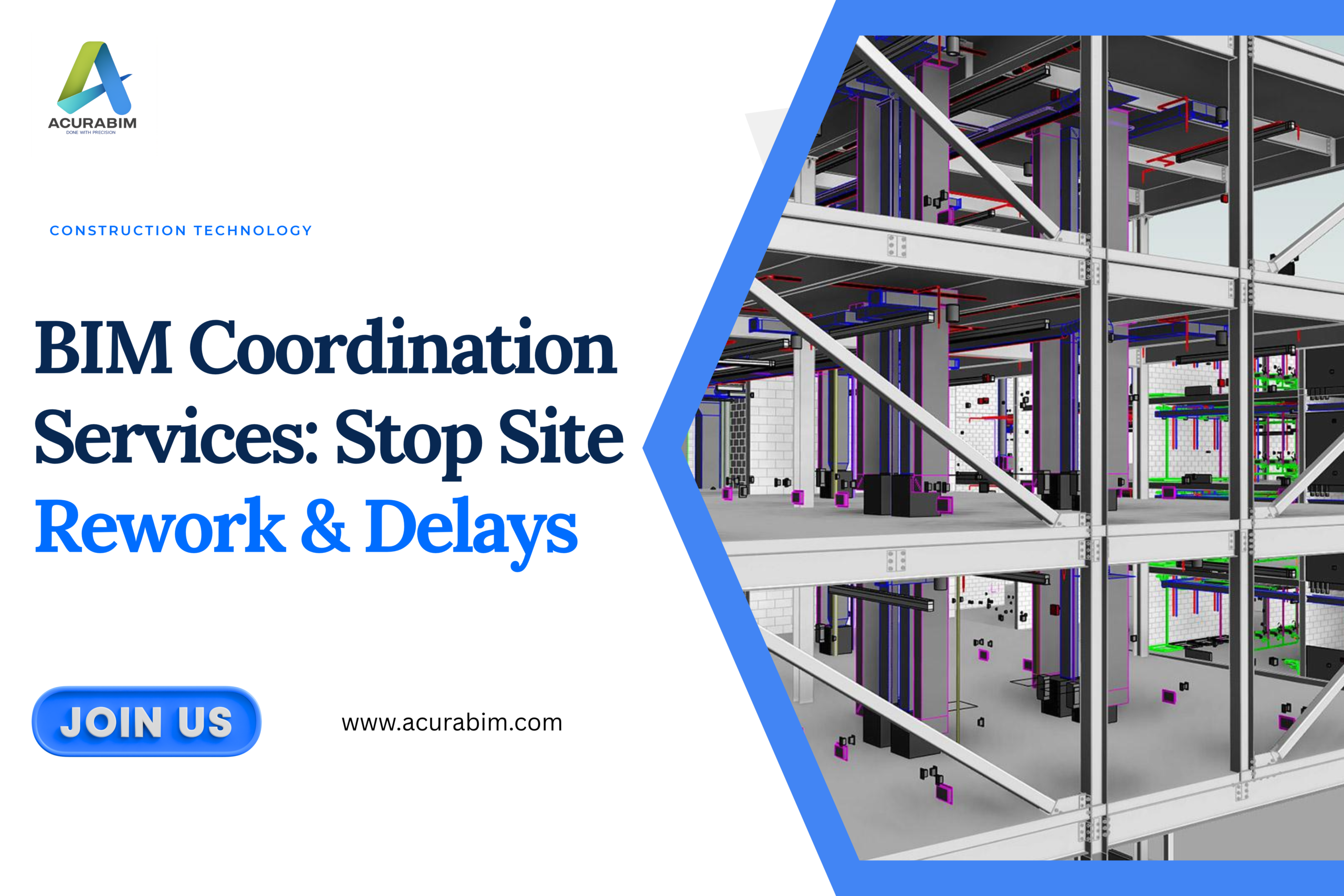
Unplanned site rework and cascading schedule delays remain two of the biggest threats to profitability in the Architecture, Engineering, and Construction (AEC) sector. When structural elements collide with mechanical runs, or when electrical conduits block plumbing paths, field crews lose valuable time waiting for Request for Information (RFI) responses, field updates, and engineering revisions. Utilizing end-to-end bim coordination services allows project managers, general contractors, and design engineering teams to identify, analyze, and resolve multi-disciplinary clashes in a virtual 3D environment long before concrete is poured, structural steel is erected, or expensive MEP equipment is shipped to the job site.
By integrating architectural, structural, and Building Services models early in the pre-construction phase, commercial construction teams achieve complete spatial alignment across all trades. This comprehensive guide explores how automated clash detection workflows, systematic constructability reviews, standardized BIM execution plans, and multi-trade model federation directly safeguard project margins, eliminate physical job site clashes, accelerate project handovers, and maintain strict delivery schedules.

The Hidden Cost of On-Site Rework in Commercial Construction
Traditional paper-based coordination and 2D CAD drafting often conceal spatial conflicts until trade contractors arrive on site to execute installation work. A single major field clash—such as an overhead HVAC supply duct colliding with a post-tensioned structural concrete beam—can instantly lead to tens of thousands of dollars in material waste, labor downtime, crane standby fees, and sudden change orders. When spatial discrepancies are discovered during active installation, field productivity grinds to a halt while trades wait for structural recalculations and revised design drawings.
When multi-disciplinary engineering teams operate in isolated silos, drawing misalignments inevitably slip through to the field. Using advanced 3D spatial models to conduct a detailed, rigorous constructability review during early pre-construction reveals underlying design inconsistencies, structural clearance shortfalls, wall sleeve omissions, and maintenance access issues long before procurement, fabrication, or site mobilization begins.
3D Clash Detection vs Traditional Coordination in AEC
For decades, general contractors relied on sequential 2D drawing overlays—stacking transparent architectural, structural, and mechanical drawings over a light table—to catch physical conflicts across building systems. While 2D overlays can reveal macro-level structural grid misalignments, they regularly miss complex 3D height clearance conflicts, pipe insulation thickness overlaps, code-mandated electrical workspace boundaries, and slope-dependent gravity drainage runs.
Modern virtual design and construction (VDC) workflows rely on spatial modeling environments to run automated collision algorithms across unified, federated 3D models. Evaluating 3D clash detection vs traditional coordination in aec demonstrates undeniable operational and financial advantages:
- Detection Speed and Scale: Automated clash engines scan tens of thousands of individual building components across all sub-trades in a matter of minutes, whereas manual drawing reviews require weeks of tedious, error-prone human audit hours.
- Micro-Level Accuracy: Multi-disciplinary model federation flags subtle, micro-level collisions—such as small-diameter electrical conduits clipping cold-formed wall framing—that paper drawing reviews almost universally miss.
- Transparent Resolution Tracking: Identified spatial issues are assigned explicit XYZ spatial coordinates, priority status ranks, severity classifications, and designated trade owners within a centralized issue tracking dashboard, eliminating finger-pointing and ambiguity across trade subcontractors.
- Enhanced Constructability Visualizations: Project stakeholders, trade leads, and field superintendents can virtually walk through complex mechanical rooms and ceiling plenums, verifying structural access points before physical assembly begins.
Understanding Hard and Soft Clash Detection in Multi-Disciplinary Workflows
To maximize pre-construction efficiency and deliver a flawless digital twin, spatial analysis is divided into two distinct conflict categories: hard and soft clash detection.
Hard Clash Analysis (Physical Intersections)
A hard clash occurs when two distinct building components physically intersect or occupy the exact same spatial coordinates within the 3D model environment. Common examples include:
- A heavy structural steel beam passing through a main hydronic supply line.
- An underground sanitary gravity pipe running directly through a reinforced concrete pile cap.
- Electrical cable trays cutting through structural shear walls without pre-planned wall sleeves or fire-rated openings.
Resolving hard clashes virtually prevents physical field destruction, cutting, core-drilling, and costly re-fabrication during structural framing and MEP rough-ins.
Soft Clash Analysis (Clearance & Serviceability Buffers)
A soft clash—often referred to as a clearance or space clash—occurs when building components do not physically intersect, but violate mandatory space buffers required for safety, insulation, isolation, or operational maintenance. Examples include:
- High-voltage electrical conduit lines routed too close to hot water supply pipes without proper thermal separation.
- An inline mechanical pump installed without sufficient workspace clearance for technicians to pull the motor shaft during routine maintenance.
- Sprinkler pipe main headers placed so low within a ceiling plenum that they violate architectural ceiling grid height specifications or code clearance minimums.
By establishing strict tolerance rules during initial BIM setup, professional spatial coordination ensures that building components fit together physically while remaining fully accessible for facility management throughout the building’s operational lifecycle.
How BIM Coordination Services Reduce Site Rework and Project Delays
Integrating structured coordination workflows directly targets and eliminates the root causes of job site budget overruns and schedule slippage. Analyzing how bim coordination services reduce site rework and project delays reveals five core operational drivers:
1. Drastic Reduction in Field RFIs and Change Orders
Resolving spatial conflicts in a virtual environment prevents the avalanche of field-generated Requests for Information (RFIs) and emergency design change orders during active construction. Field crews receive completely vetted, conflict-free construction drawings, enabling them to execute installation continuously without costly downtime.
2. Streamlined Off-Site Prefabrication and Modular Construction
Accurate, fully coordinated models allow mechanical, electrical, and plumbing trade contractors to pre-assemble duct runs, pipe spools, valve banks, and modular equipment racks in controlled off-site factory conditions. Off-site prefabrication significantly reduces job site labor density, minimizes material clutter, improves safety metrics, and dramatically speeds up on-site installation schedules.
3. Optimized Multi-Trade Work Sequencing (4D Scheduling)
Constructability reviews allow project managers to simulate installation sequencing in 4D (combining 3D spatial models with time-based construction schedules). Trade contractors understand precisely when, where, and in what order to deploy their installation crews, avoiding site congestion, trade stacking, and rework caused by out-of-sequence construction.
4. Significant Material Waste Reduction
Field-modifying heavy ductwork, structural steel connections, or large-diameter piping runs creates immense scrap material waste and drives up disposal costs. Fully coordinated models yield exact, automated material takeoff schedules, ensuring sub-contractors procure precise material quantities and eliminate job site scrap.
5. Superior Long-Term Facility Quality and Compliance
A clash-free, coordinated model guarantees that building infrastructure systems are installed strictly as designed by primary engineering consultants. This ensures uncompromised structural integrity, acoustic performance, code-compliant egress paths, and optimized mechanical air distribution throughout the built environment.
The Revit BIM Coordination Process for Commercial Buildings
Creating a fully resolved commercial building model requires a disciplined, multi-stage workflow executed across every architectural and engineering discipline. Implementing a standard revit bim coordination process for commercial buildings involves four distinct phases:
Phase 1: Disciplinary Model Authoring and Standard Setup
Architectural, structural, civil, and MEP trade modeling teams author their respective native 3D models using advanced authoring platforms such as Autodesk Revit. Each discipline adheres to project-specific BIM Execution Plans (BEP), setting strict Level of Development (LOD) benchmarks ranging from design intent models (LOD 300) to detailed, fabrication-ready geometry (LOD 400).
Phase 2: Model Aggregation and Shared Coordinate Alignment
Individual discipline models are linked into a centralized federated coordination environment. Establishing unified shared coordinate systems, origin points, control grids, and floor elevation benchmarks is vital to ensure that structural columns, architectural curtain walls, and MEP distribution lines map accurately in 3D space across all discipline files.
Phase 3: Automated Clash Auditing and Issue Resolution
The federated model is imported into auditing engines to perform automated spatial clash matrix tests. BIM coordinators facilitate regular multi-trade coordination meetings where designers and trade superintendents review flagged collisions, establish resolution strategies, and update native Revit geometry to eliminate identified issues.
Phase 4: Sign-Off and Spool/Shop Drawing Generation
Once the federated model passes all constructability rules and spatial clear checks, discipline leaders issue formal BIM sign-offs. Coordinated 3D models are then used to extract highly accurate field shop drawings, sleeve location maps, hangar layout files, and prefabrication spool sheets ready for site deployment.
Implementing an Effective MEP BIM Clash Detection Services Strategy
Commercial construction projects involve densely packed ceiling plenums and mechanical risers carrying complex mechanical, electrical, plumbing, and fire protection systems. Partnering with specialized mep bim clash detection services for general contractors ensures these highly congested service corridors are organized logically and efficiently.
To prevent continuous design disputes during spatial coordination meetings, BIM managers enforce a strict MEP trade coordination matrix. This matrix establishes routing priority hierarchy based on material flexibility, code requirements, gravity slope dependencies, and installation costs:
| Priority Rank | Building Trade System | System Characteristics & Routing Constraints |
| Priority 1 | Gravity Plumbing & Drainage | Rigid slope requirements; non-negotiable fall angles dictate primary spatial right-of-way. |
| Priority 2 | Heavy HVAC Supply/Exhaust Ducts | Large physical cross-sections; difficult and expensive to offset or reroute around other services. |
| Priority 3 | Fire Protection Main Lines | Rigid pipe distribution; subject to strict code coverage rules, head placements, and main slope mandates. |
| Priority 4 | High-Pressure Hydronic & Steam Lines | Smaller-diameter insulated piping runs; offer moderate flexibility around major ductwork headers. |
| Priority 5 | Electrical Cable Trays & Conduit | Highly flexible; can be easily split, dropped, or routed around rigid mechanical and plumbing lines. |
Establishing clear trade hierarchy rules early in pre-construction prevents endless model revisions, reduces friction among trade subcontractors, and speeds up sign-off schedules.
The Navisworks Clash Detection Workflow Explained
While initial modeling takes place in authoring software like Revit, multi-disciplinary model aggregation, heavy spatial collision audits, and issue management workflows are managed inside dedicated audit environments like Autodesk Navisworks. Following a structured Navisworks clash detection workflow keeps issue management efficient across large-scale commercial projects.
Step 1: Model Export and Lightweight Cache Conversion
Native design files (.RVT, .DWG, .IFC) are exported into lightweight Navisworks Cache (.NWC) formats. Lightweight file conversions allow BIM coordinators to navigate massive multi-gigabyte commercial building models smoothly without performance lag.
Step 2: Custom Search Set and Matrix Creation
Rather than running indiscriminate tests across all model elements—which produces thousands of irrelevant data points—coordinators build custom Search Sets. Components are grouped by building level, zone, discipline, and trade system (e.g., Level 2 Structural Framing vs Level 2 Supply Air Ducts).
Step 3: Running Rules-Based Clash Matrix Audits
Coordinators configure rules within the Clash Detective tool to cross-examine specific Search Sets using predetermined clearance thresholds (e.g., setting a 25mm hard clash tolerance or a 300mm soft maintenance clearance buffer around electrical transformers).
Step 4: Intelligent Issue Grouping and Filtering
A single misplaced main supply duct passing through a structural stud wall might generate fifty individual clash flags in a raw report. Experienced BIM coordinators group these related collisions into a single actionable issue item, ensuring progress reports remain clear, focused, and manageable.
Step 5: BCF Export and Native Model Synchronization
Grouped clash issues are assigned to designated trade contractors along with high-resolution camera angles, floor grid locations, and unique element ID tags. Coordinators export these items via BIM Collaboration Format (BCF) files, allowing modeling teams to import issues directly back into native Revit software for instant, pinpoint location fixes.
Why General Contractors Need Professional BIM Coordination Services
As commercial building envelope designs grow more complex and project delivery schedules tighten, managing advanced spatial coordination in-house can overfill general contracting teams. Partnering with a dedicated external BIM services firm yields substantial operational and cost benefits:
- Reduced Overhead & Software Expenses: Eliminate the need for high-end dedicated hardware workstations and ongoing, expensive BIM software licensing fees.
- Access to Specialized VDC Expertise: Tap into experienced BIM leads and coordinators skilled in advanced spatial navigation, multi-trade matrix setup, and conflict resolution across complex commercial builds.
- Unbiased Third-Party Facilitation: Neutral third-party coordinators keep trade subcontractors focused on collaborative problem-solving during weekly coordination meetings, avoiding trade bias.
- Scalable Modeling Resources: Easily scale modeling capacity up or down to match peak pre-construction demands across multiple simultaneous active jobsites without hiring permanent headcount.
By partnering with professional revit bim coordination experts, general contracting firms ensure a smooth transition from early architectural concepts to clean, clash-free, field-ready construction drawings.
Optimize Your Project Delivery with Acura BIM Services
At Acura BIM, we specialize in delivering precise, constructible, and completely clash-free 3D BIM models designed to meet the rigorous demands of general contractors, MEP subcontractors, engineering consultants, and real estate developers worldwide. Our team of skilled BIM coordinators, modelers, and VDC specialists helps project managers eliminate site rework, streamline multi-trade workflows, and keep projects running on budget and schedule.
Our Comprehensive Capabilities
- Multi-Disciplinary Model Federation: Unifying Architectural, Structural, MEPF, Civil, and Infrastructure models into a single, seamless digital source of truth.
- Advanced Clash Detection & Resolution: Detailed Navisworks analysis tracking hard physical collisions, soft clearance violations, and 4D workflow conflicts.
- Constructability & Spatial Audits: In-depth model sanity audits verifying system maintenance access, structural sleeve placements, and code compliance.
- Fabrication & Shop Drawing Production: Extracting accurate, field-ready installation sheets, prefabrication spool maps, and sleeve location drawings directly from LOD 400 models.
Ready to protect your construction margins, optimize trade installation sequences, and stop site delays before they start? Discover how our full-suite BIM Coordination Services can transform your next commercial build.
Explore our related BIM and VDC engineering solutions:
- Learn how our specialized MEP BIM Services streamline complex mechanical, electrical, and plumbing installations.
- Read about our expert Structural BIM Modeling solutions for accurate concrete, steel framing, and rebar detailing.
- Visit our About Us page to learn more about our company background, mission, and global project portfolio.
Frequently Asked Questions (FAQs)
What are BIM coordination services?
BIM coordination services involve aggregating 3D digital models from multiple design disciplines—including Architectural, Structural, Civil, Mechanical, Electrical, Plumbing, and Fire Protection—into a single federated model. Advanced software engines audit the model to identify, analyze, and resolve physical clashes and clearance violations virtually before physical construction begins on site.
How do BIM coordination services differ from traditional CAD drafting?
Traditional CAD drafting relies on two-dimensional drawing overlays and manual reviews to spot drawing mismatches, which routinely miss complex 3D height clearance conflicts, system insulation thicknesses, and maintenance access buffers. BIM coordination services use dynamic 3D geometry and automated software algorithms to detect hard and soft clashes across all systems, resulting in far higher accuracy and dramatically lower field rework.
What is the difference between a hard clash and a soft clash?
A hard clash occurs when two building elements physically intersect or share the exact same spatial coordinates, such as a plumbing pipe passing directly through a solid concrete column. A soft clash occurs when an element violates a required clearance zone, safety buffer, or maintenance access space, such as an electrical junction box placed too close to a wall or a duct blocking access to a mechanical control valve.
At what project stage should BIM coordination begin?
BIM coordination delivers the highest return on investment when introduced during the detailed design and early pre-construction phases (around LOD 300). Resolving spatial conflicts before subcontracts are finalized, materials are ordered, or shop drawings are issued ensures smooth off-site prefabrication, precise material purchasing, and uninterrupted site execution.
How does BIM coordination enable off-site prefabrication?
BIM coordination provides trade contractors with fully validated, dimensional 3D geometry. Because spatial conflicts are resolved in the virtual model prior to installation, MEP sub-contractors can fabricate duct runs, pipe spools, and electrical racks off-site in factory conditions with total confidence that components will fit correctly when delivered to the job site.