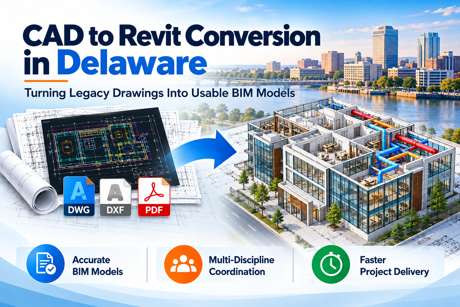
Engineering teams, project managers, and general contractors across Delaware face a persistent challenge: managing outdated, disconnected design records. Whether upgrading historic commercial real estate in Wilmington or executing large-scale civic projects near Dover, relying on legacy 2D CAD drawings or scanned paper PDFs often introduces costly friction into project lifecycles.
Executing CAD to Revit Conversion in Delaware: Turning Legacy Drawings Into Usable BIM Models bridges the gap between historical design archives and modern construction standards. Converting legacy drawings into intelligent, parametric Revit models transforms flat lines into data-rich building information models (BIM). Consequently, project stakeholders reduce design discrepancies, mitigate field change orders, and streamline collaboration across all architectural, structural, and MEP engineering disciplines.
Why Delaware Construction Projects Need CAD to BIM Delaware Migration
The construction landscape in Delaware is evolving rapidly. Consequently, project managers and engineering consultants require greater precision, faster turnaround times, and seamless coordination across multidisciplinary teams.
Traditional 2D CAD workflows rely on disconnected floor plans, elevations, and section views. When a modification is made to a floor plan, drafting teams must manually adjust every related section and elevation across multiple DWG files. In contrast, migrating from CAD to BIM Delaware workflows creates a single source of truth. Every wall, door, beam, and duct is represented as a parametric object containing geometric and functional metadata.
Furthermore, state infrastructure directives, historic preservation standards, and commercial retrofits require comprehensive digital records. Converting flat CAD files into parametric BIM assets ensures that civil contractors and general contractors possess exact spatial data before breaking ground.
The Hidden Costs of Relying on Legacy Drawings and PDF Files
Continuing to rely on unverified legacy drawings or static paper plans exposes construction teams to substantial financial and operational risks:
- Spatial Inaccuracies & Clash Risks: Flat 2D CAD drawings do not automatically detect spatial collisions between structural framing and MEP ductwork. As a result, field crews often discover clashes during installation, leading to expensive delay claims.
- Loss of Design Data: Older PDF scans and legacy vector files often suffer from scale distortions, missing layer conventions, or broken reference paths (XREFs).
- Inefficient Quantity Takeoffs: Estimators using paper or CAD files must manually count materials, increasing the likelihood of human error during bidding.
- Outdated Facility Records: Facility managers struggle to maintain assets without an accurate 3D spatial register, driving up long-term operational costs.
According to research from the National Institute of Building Sciences (NIBS), implementing structured BIM standards significantly mitigates field rework costs and reduces baseline project schedules.
Technical Overview: PDF to Revit Conversion vs. DWG Vector Migration
Not all source files are created equal. Converting legacy documentation into fully parametric models requires distinct technical approaches depending on the quality and format of the input data.
1. Vector DWG/DXF Migration
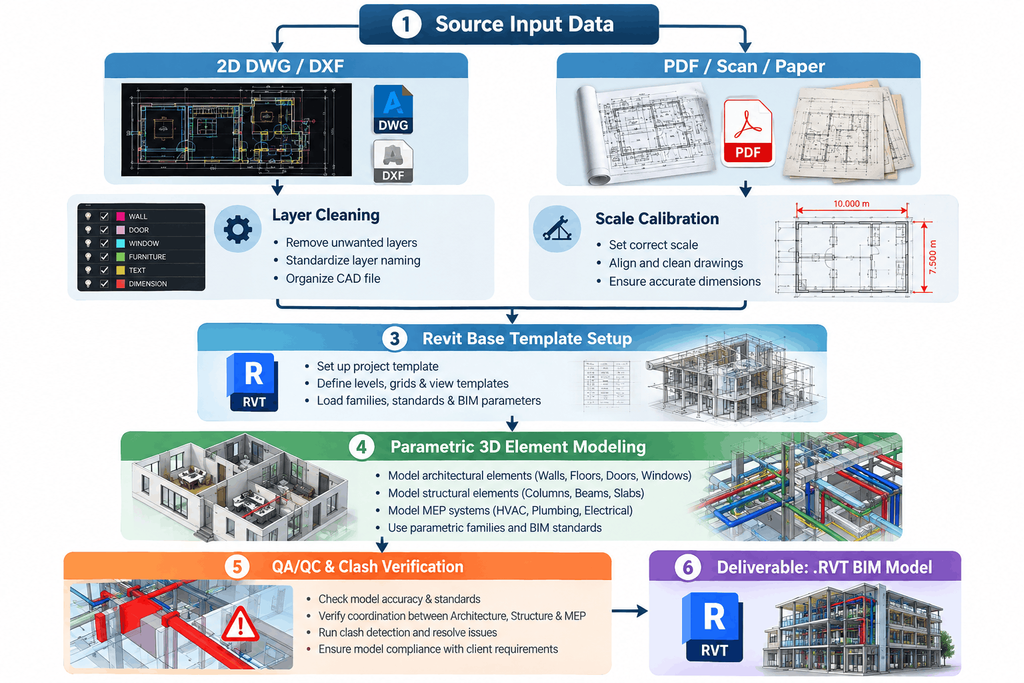
When working with original AutoCAD DWG or DXF files, modeling technicians inspect line weights, clean up unreferenced layers, align coordinate systems, and establish project datum levels. Because geometry is already digitized, conversion teams can directly align elements against Revit wall types, structural grids, and floor slabs.
2. PDF to Revit Conversion & Paper Scanning
When original CAD files are unavailable, project teams turn to PDF to Revit conversion. Raster PDFs or scanned blueprints must first be scaled, cleaned, and calibrated within the BIM environment. Specialized modeling professionals verify structural centerlines and dimension callouts manually to resolve scan distortion before generating high-fidelity parametric components.
Core Capabilities of Professional Revit Modeling Services
Outsourcing or partnering with an expert team for Revit modeling services provides project managers and contractors with specialized technical expertise without requiring costly in-house software infrastructure.
Professional conversion workflows cover four primary areas:
Architectural BIM Modeling
- Wall assemblies, curtain systems, doors, windows, and interior finishes.
- Adaptive building components tailored to historic Delaware architecture.
- Creation of accurate construction documentation sets derived directly from the 3D model.
Structural BIM Modeling
- Cast-in-place concrete, steel framing schedules, foundations, and rebar details.
- Verification of structural grids against original 2D CAD drawings.
MEP (Mechanical, Electrical, Plumbing) Modeling
- Routing for HVAC ductwork, piping networks, cable trays, and plumbing lines.
- Pre-construction spatial coordination to ensure mechanical clearances meet Delaware building codes.
As-Built BIM for Facility Management
- Converting existing drawings into accurate digital twins post-construction.
- Incorporating Asset Data (COBie parameters) directly into geometric elements for lifecycle management.
To explore how tailored modeling fits into your operational workflows, review our specialized Architectural BIM Services and MEP BIM Coordination Solutions.
Step-by-Step Methodology: Converting Legacy CAD to Usable BIM Models
To achieve zero-error deliverables, expert BIM service providers follow a structured, multi-phase conversion methodology:
| Phase | Milestone / Action Items | Primary Output |
| Phase 1: Audit & Ingestion | Assess legacy CAD drawings, verify scales, resolve missing XREFs, and establish project scope. | Audit Report & Setup Strategy |
| Phase 2: Template Configuration | Define Delaware local building code parameters, project units, shared coordinates, and family libraries. | Configured .RVT Template |
| Phase 3: 3D Parametric Modeling | Convert 2D geometry into intelligent 3D BIM assets (architectural, structural, and MEP). | Preliminary 3D Model |
| Phase 4: Quality Assurance & QA/QC | Perform rigorous clash detection, dimension cross-checks, and Level of Detail (LOD) verification. | QA/QC Audit Log |
| Phase 5: Model Handover | Deliver fully coordinated Revit files, 3D CAD exports, and updated 2D sheet sets. | Final .RVT, .NWD & Sheet Sets |
Step 1: Input Data Audit and Cleanup
Before importing files into Revit, BIM specialists review incoming legacy assets. They clean drawing units, purge unused blocks, unify scale variations, and verify dimensions against site measurements or survey data.
Step 2: Setting Coordinates and Project Levels
A vital step in legacy CAD conversion is establishing accurate real-world coordinates and level markers. Establishing proper datum alignments early prevents model displacement issues during downstream coordination.
Step 3: Parametric Element Creation
Rather than simple 3D mesh extrusion, elements are modeled as parametric Revit families containing material data, fire ratings, structural load criteria, and thermal properties.
Step 4: Quality Assurance and Clash Detection
Using coordination platforms like Autodesk Navisworks, modeling engineers perform Automated Clash Detection to isolate intersections between mechanical conduits, plumbing runs, and structural beams. According to standard guidelines published by the U.S. General Services Administration (GSA) BIM Guide, pre-construction spatial coordination drastically minimizes change orders during field assembly.
Key Benefits for Delaware Project Stakeholders
Whether overseeing commercial development in Wilmington or managing municipal infrastructure projects across New Castle County, adopting structured BIM conversion delivers tangible return on investment across every project stage:
- For Project Managers: Greater schedule predictability, precise material estimates, and centralized communication across owner and sub-contractor groups.
- For Engineering Consultants: Reduced design risk, simplified compliance checks, and automated update capabilities across all sheet drawings.
- For General Contractors: Clear visual sequencing (4D BIM integration), pre-fabrication opportunity identification, and fewer field RFI submissions.
- For Civil Contractors: Smooth alignment between site topography, utility lines, and structural foundations.
Learn more about how integrated modeling streamlines project workflows by visiting our BIM Coordination Services overview.
Partner with Acura BIM for CAD to Revit Conversion in Delaware
Transitioning from outdated paper blueprints or legacy 2D CAD files into precise, cloud-ready Revit models requires deep technical domain expertise and dedicated quality control. At Acura BIM, we specialize in transforming complex, fragmented architectural and engineering records into reliable, data-rich BIM assets tailored specifically to your project requirements.
Whether you are preparing for a major renovation, fulfilling strict municipal submittal standards, or streamlining pre-construction coordination across Delaware, our modeling specialists deliver high-precision BIM solutions on schedule and within budget.
Ready to modernize your legacy drawings into intelligent, actionable 3D Revit models?
Contact Acura BIM Today for a Custom Project Quote and discover how our engineering team can streamline your next construction project.
Frequently Asked Questions (Q&A)
What source file formats can be converted into Revit BIM models?
We convert a wide range of legacy inputs, including AutoCAD files (.DWG, .DXF), raster and vector PDF documents, hand-drawn paper blueprints, tiff images, and point-cloud 3D laser scan data.
What Level of Detail (LOD) can be achieved through CAD to Revit conversion?
Models can be developed to any standard Level of Detail required for your project stage—ranging from LOD 100 (schematic design) up to LOD 400 (fabrication and assembly) and LOD 500 (as-built facility management).
How long does a typical CAD to Revit conversion project take in Delaware?
Timeline depends on total square footage, project complexity, and target LOD. Small commercial or residential projects often take 3 to 5 business days, whereas large-scale industrial or institutional facilities are scoped across tailored milestone phases.
Why is simple automated PDF-to-CAD conversion insufficient for BIM workflows?
Automated conversion software produces unorganized 2D vector lines without parametric intelligence. True BIM conversion requires skilled BIM engineers to interpret design intent, assign correct object parameters, verify structural integrity, and ensure full spatial coordination.