Uncategorized

Shortcuts In Revit

Introduction: As an architectural, engineering, or construction professional, you likely spend a significant amount of time working with Revit, a powerful software tool for building information modelling (BIM). To maximize your productivity and streamline your workflows, it’s essential to familiarize yourself with the various keyboard shortcuts available in Revit. These shortcuts can help you navigate the software, manipulate objects, and perform various tasks more efficiently. One of the most useful keyboard shortcuts in Revit is the “Escape” key, which allows you to cancel a command or exit a tool. This can be especially helpful if you accidentally enter a command or get stuck in a tool that you didn’t intend to use. Another essential shortcut is the “Tab” key, which allows you to toggle between open views and sheets. This can be especially useful when you’re working on multiple views or sheets at the same time and need to quickly switch between them. The “Ctrl” key is also crucial in Revit, as it allows you to perform various actions such as copying and pasting elements, creating duplicate elements, and aligning objects. For example, you can use “Ctrl + C” to copy an element, “Ctrl + V” to paste it, and “Ctrl + A” to align it with another element. The “Spacebar” is another key that can be very useful in Revit. You can use it to pan and zoom in and out of views, as well as to access various tools and commands. For example, you can press the “Spacebar” to access the “Select” tool, or hold it down to access the “Orbit” tool. There are many other keyboard shortcuts available in Revit, including ones for modifying objects, managing views and sheets, and working with text and dimensions. Some of the most useful ones include: “Escape” – cancel a command or exit a tool “Tab” – toggle between open views and sheets “Ctrl + C” – copy an element “Ctrl + V” – paste an element “Ctrl + A” – align an element with another element “Ctrl + Shift + W” – create a copy of a selected element “Ctrl + Shift + M” – mirror a selected element “Ctrl + Shift + R” – rotate a selected element “Ctrl + Shift + L” – lock a selected element “Ctrl + Shift + H” – hide a selected element “Ctrl + Shift + I” – isolate a selected element “Ctrl + Shift + E” – explode a selected element “Ctrl + Shift + J” – join two or more elements “Ctrl + Shift + T” – add text to a view “Ctrl + Shift + D” – add dimensions to a view “Spacebar” – access the “Select” tool or hold down to access the “Orbit” tool “F2” – access the “Modify” tool “F5” – access the “Properties” palette “F7” – access the “Level” tool “F8” – access the “Wall” tool It’s worth noting that some of these keyboard shortcuts may differ depending on your operating system or the version of Revit you’re using. It’s always a good idea to consult the Revit documentation or online resources to confirm the exact keyboard shortcuts for your specific setup. To maximize your productivity with Revit keyboard shortcuts, it’s essential to take the time to learn and memorize the ones that you use most frequently. You may also want to consider customizing the keyboard shortcuts to better suit your workflows and preferences. This can typically be done through the “Keyboard Shortcuts” dialog in the “Options” menu. In conclusion, keyboard shortcuts are a crucial tool for increasing your productivity and efficiency when working with Revit. By familiarizing yourself with the various shortcuts available and customizing them to suit your needs, you can significantly streamline your workflows and get more done in less time.

Shortcuts In Revit Read More »
Clash Detection In Naviswork

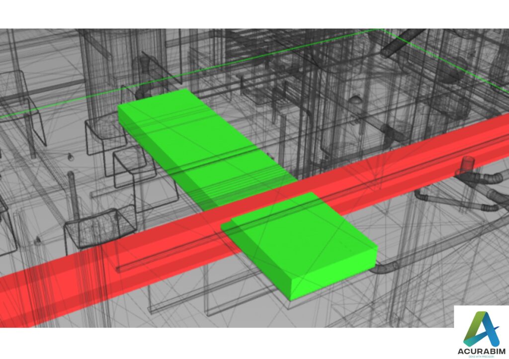
Introduction: Navisworks is a 3D design review software that is commonly used in the construction industry for clash detection, which is the process of identifying conflicts or collisions between different components or systems in a building or infrastructure project. By using Navisworks, construction professionals can identify and resolve issues before they become problems on the construction site, which can save time and money. Here is a detailed guide on using Navisworks for clash detection: Import the 3D models into Navisworks To begin the clash detection process, you need to import the 3D models of the building or infrastructure into Navisworks. These models can be in the form of AutoCAD, Revit, or any other 3D file format that Navisworks supports. Set up the clash detection rules Once the models are imported, you can set up the clash detection rules. These rules define the types of clashes that Navisworks should look for, such as clashes between structural components, MEP systems, or any other type of conflict that you want to identify. Run the clash detection analysis After setting up the clash detection rules, you can run the analysis to identify the clashes between the different components in the model. Navisworks will display the clashes in the form of red markers on the model, with each marker representing a different clash. Review and resolve the clashes Once the clashes have been identified, you can review them one by one and resolve them as needed. This may involve adjusting the design of certain components, relocating them to a different location, or finding a different solution. Navisworks allows you to make changes to the model and rerun the clash detection analysis to ensure that all clashes have been resolved. Create reports and document the process Once the clash detection process is complete, you can generate reports in Navisworks that summarize the results of the analysis, including the number of clashes found, the types of clashes, and the resolution of each clash. These reports can be useful for documenting the process and demonstrating to stakeholders that the project has been thoroughly reviewed and any potential issues have been addressed. Conclusion: In conclusion, Navisworks is a powerful tool for clash detection in the construction industry. By using Navisworks, construction professionals can identify and resolve conflicts between different components and systems in a building or infrastructure project, which can save time and money and ensure a successful project.

Clash Detection In Naviswork Read More »

Template in Revit

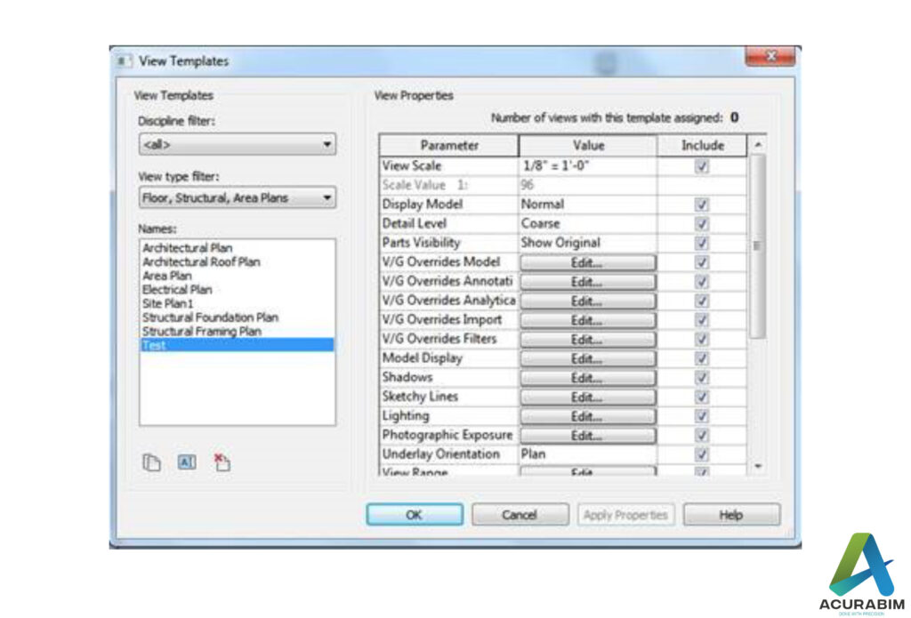
Introduction: Revit is a popular Building Information Modelling (BIM) software that is widely used in the architecture, engineering, and construction (AEC) industry. One of the key features of Revit is the ability to create and use templates, which are pre-defined sets of settings, standards, and content that can be used to streamline the modelling process and ensure consistency in the design. Here is a detailed guide on creating and using Revit templates: Determine the purpose of the template Before creating a Revit template, it is important to determine the purpose of the template and what you want to achieve with it. Some common uses of Revit templates include: Setting up the default project settings, such as the units, project location, and site data Establishing a consistent set of drafting and annotation standards Pre-loading a set of commonly used families and symbols Setting up project-specific workflows and processes Create a new template file To create a new template file in Revit, go to the “File” menu and select “New.” In the “New” dialog box, select the “Template” option and choose the desired version and template type (such as “Imperial” or “Metric”). Then, give the template a name and select a location to save it. Customize the template settings Once the template file is created, you can customize the settings to meet the needs of your project. To access the template settings, go to the “Manage” tab and click on the “Additional Settings” button. From there, you can customize various settings such as the project units, drafting standards, and default materials. Add content to the template You can also add content to the template file, such as families, symbols, details, and schedules. To do this, go to the “Insert” tab and use the various tools and options available to add the desired content to the template file. Save and distribute the template Once you have customized the template and added the desired content, you can save the template file and distribute it to other users in your organization. To do this, go to the “File” menu and select “Save As.” In the “Save As” dialog box, select the “Template” option and choose a location to save the template file. You can then share the template file with other users in your organization through email, a shared network drive, or other methods. Conclusion: In conclusion, Revit templates are a useful tool for streamlining the modelling process and ensuring consistency in the design. By creating and using Revit templates, you can save time and effort, improve efficiency, and deliver higher quality projects.

Template in Revit Read More »

Family Creation In Revit

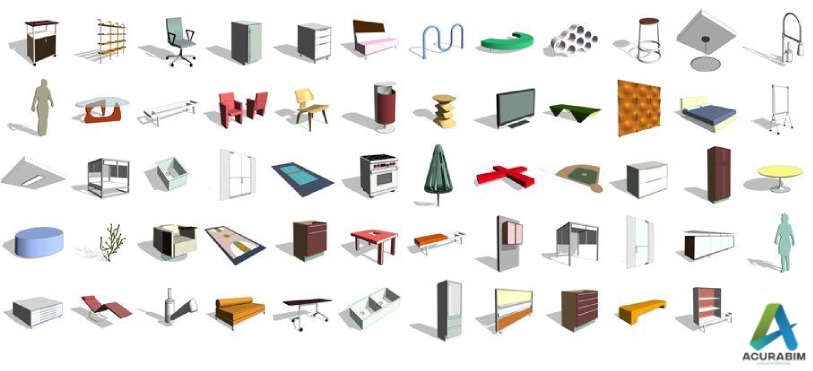
Family Creation In Revit: Creating families in Autodesk Revit can be a powerful tool for adding customized elements to your building design projects. Families are essentially pre-made objects that can be inserted into your Revit model and behave just like any other element, such as walls or doors. The main advantage of using families is that they allow you to quickly add complex or unique objects to your model without having to manually draw them each time. In this blog, we’ll cover the basics of creating families in Revit, including an overview of the different types of families, the steps involved in creating a family, and some tips and best practices to follow. Types of Families in Revit Before diving into the creation process, it’s important to understand the different types of families that are available in Revit. There are three main types of families: System families: These are the basic building blocks of your Revit model, such as walls, floors, roofs, and ceilings. System families are pre-made and cannot be edited or modified. Loadable families: These are pre-made families that can be inserted into your model from the Revit library or from a file on your computer. Loadable families can be modified to some extent, but they cannot be created from scratch. In-place families: These are families that are created directly in your Revit model, rather than being inserted from a library or file. In-place families are completely customizable and can be created to meet your specific needs. Creating a Family in Revit To create a new family in Revit, follow these steps: In the Revit ribbon, go to the “Create” tab and click on the “Family” button. This will open the “New Family” dialog box. In the “New Family” dialog box, choose the type of family you want to create. You can choose between three types: Generic Model, Generic Annotation, or Loadable Annotation. Select the appropriate template for your family. If you’re creating a generic model family, you’ll have the option to choose between several different templates, such as walls, floors, or windows. If you’re creating a generic annotation family, you’ll have the option to choose between text, dimensions, or symbols. Click “OK” to create the new family. This will open the “Family Editor” window, which is where you’ll create and customize your family. In the “Family Editor” window, use the various tools and features to create your family. This may involve drawing lines, arcs, and circles, as well as using various constraints and parameters to define the behaviour of your family. Tips and Best Practices for Creating Families in Revit Here are a few tips and best practices to keep in mind when creating families in Revit: Start simple: It’s often best to start with a simple family and gradually add more complexity as you become more comfortable with the family creation process. This will help you avoid becoming overwhelmed and will make it easier to troubleshoot any issues that arise. Use good modelling practices: When creating your family, be sure to follow good modelling practices, such as using consistent and logical naming conventions, keeping your model organized and easy to understand, and avoiding unnecessary geometry. Test your family: Before you finish your family, be sure to test it in a Revit project to ensure that it behaves as intended. This will help you identify any issues or bugs that need to be addressed. Save and backup your family: As with any important project, be sure to save your family regularly and create backups

Family Creation In Revit Read More »

Level of Detail/Development in Revit Modelling

Level of Detail/Development in Revit Modelling: The Level of Detail/Development (LOD) describes the overall condition of your information model at a specific stage of the design process. This contains the accompanying data as well as the graphical elements themselves. Your model should go from a very rough concept to the as-builts and record drawings over time. According to the AIA E202 contract agreement, this procedure has been standardized into five separate categories. Model Advancement: The idea of model progression lies at the heart of the five-layer LOD. It is critical to understand that not all elements will advance through the model at the same rate or be present at every level. For instance, while essential structural elements may advance through all 5 levels, fittings on mechanical systems could not exist until level 400. Additionally, different disciplines will move through the procedure at various speeds. Structure steel frequently reaches the 400 level before all mechanical has achieved the 300 level. This must be understood by the entire team, who must then create plans to prevent items from reaching the field if their final design will be impacted by model elements that have not yet been established. For instance, steel cannot be released from the 300 level until mechanical loads have been determined. This is just to ensure that the loads required to calculate the steel are accurate. It does not imply that mechanical must be finished to the same degree. Ownership of graphical objects and the data they are connected with may change as the model develops from conceptual to as-built. The changeover from one data format to another may also be a part of this. It is crucial that during this procedure, data accuracy be upheld. Simplifying LOD: At various stages of a project’s development cycle, it is crucial to have a clear description of what is contained in the information model. One of the most crucial components of a BIM-based project’s success is the understanding of expectations, roles, and duties. In order to help with this, GSA has created a number of resources. Please refer to following list to know about the model’s usable features at each stage of development (e.g., level 400 models may be used for exact pricing) LOD 100 (Conceptual) There may not be many brownfield projects that include LOD 100 because it is the beginning of a project. The conceptual design phase of a typical project is fairly comparable to LOD 100. A model will be at its most basic during this stage. A basic site layout may be present, the building will be located, and some very rudimentary evaluations may be carried out. These assessments could involve preliminary whole-site construction phasing, conceptual cost based on cost per square foot, and whole-building energy analysis. There might not always be any model data available for LOD 100. Only analytical data, 2D CAD data, or even hand drawings could be included. When compared to LOD 200 and beyond, LOD 100 is frequently completed by GSA staff or a separate architect. Any model data should, wherever feasible, be developed with the knowledge that it will eventually need to be transferred to a BIM design tool. For instance, if Revit will be used to finish the future designs (200 and 300), a tool that is compatible with Revit should be taken into account for the 100-level massing, modelling, and analysis. LOD 200 (Approximate Geometry) Schematic design and design development are comparable to LOD 200. The conceptual massing model and related data will be transformed during this phase into a model suited for the preparation of construction documents. Given that it includes both the conventional schematic design and design development activities, this is one of the phases that any model will go through that is the longest. By the end of this 200-level course, a model including the approximate number, size, position, and systematic relationships of the majority of the deployed items will exist. Basic information will be initially put in for all object’s data. Even if precise item information might not yet be accessible, space claims for each object or system should at the very least be taken into consideration. During this phase, preliminary high-level coordination should be taking place. Planning should be the main emphasis of coordination, not violent conflicts (e.g., vertical space allotment for utilities not pipe-on-pipe collisions). According to the project’s BEP, this coordination should be cross-disciplinary and conducted at project coordination meetings. LOD 300 (Precise Geometry) LOD 300, the stage where a design starts to precisely resemble what will be built, is comparable to construction papers. The geometry of specific pieces is verified to be 3D. Dimensions, capabilities, and relationships of the object are specified. Upon completion of level 300, a model with the precise number, size, placement, and logical relationships of every object that will eventually be placed will be available. All necessary fundamental data will be entered into the data about all items. There shouldn’t be any rough forms or space demands for any installed object (space claims to protect space for code compliance or similar will still be present). Throughout this phase, individual object level cooperation should be occurring. Major harsh conflicts should be the focus of coordination (e.g., pipe-on-pipe collisions). In this time, the AE and Constructors ought to be present at the coordination sessions. LOD 400 (Precise Geometry) When manufacturing and assembly can be driven directly from the model, LOD 400 is attained. The level 400 information model is produced exclusively by the trade partners with input from the AE for the majority of item types. The design information model frequently becomes inactive at this stage of development while fabrication models are derived from them on a different CAD platform. For design or as-built models, different tools are needed than for manufacturing level models. Trade scheduling is one of LOD 400’s main differences. At levels 100 through 300, various trades are finishing the stages at various times. For instance, the crafts of architectural components, structural steel and foundations, and

Level of Detail/Development in Revit Modelling Read More »

Scroll to Top