Scan to BIM

Export Sketchup file to Google Earth

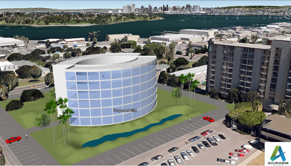
Introduction: SketchUp is a powerful 3D modelling software that is widely used by architects, designers, and other professionals in the construction and design industry. One of the great features of SketchUp is the ability to export your model to Google Earth, allowing you to view your design in a real-world context. Exporting a SketchUp file to Google Earth is a simple process that can be done in just a few steps. Make sure that you have both SketchUp and Google Earth installed on your computer. Sketchup file is converted to KML file, & thus that file Is imported in Google Earth. A brief explanation for KML file is given in following para. About KML File: A KML file is a type of file that is used to store geographic data and information in a format that can be easily read by a variety of mapping and spatial analysis software. KML stands for “Keyhole Markup Language,” and it is a file format that was developed by Google for use with its Google Earth software. One of the key features of KML files is that they allow you to store and display geographic data in a way that is easily understood by both humans and computers. KML files use a system of tags and attributes to describe the data that they contain, and this makes it easy for software programs to interpret and display the data in a meaningful way. There are many different types of data that can be stored in a KML file, including points, lines, and polygons that represent features on the earth’s surface, as well as information about the appearance and behaviour of these features. For example, you can use a KML file to store information about the location and appearance of a building, or you can use it to store data about a network of roads or a set of geographic boundaries. KML files are often used in a variety of applications, including GIS software, mapping websites, and mobile apps. They are also commonly used to share geographic data with others, as KML files can be easily shared and viewed by anyone who has access to a KML-compatible application. Overall, KML files are an important tool for storing and sharing geographic data, and they are widely used in a variety of fields, including geography, mapping, and spatial analysis. Whether you are working on a professional project or simply exploring the world around you, KML files can be a valuable resource for understanding and visualizing the earth’s surface. To export your SketchUp file to Google Earth, follow these steps: Open your SketchUp model in SketchUp. Go to the “File” menu and select “Export.” In the export dialog box, select “Google Earth (KML)” as the file type. Choose a location to save the KML file, and click “Export.” Open Google Earth and go to the “File” menu. Select “Open,” and choose the KML file that you just exported from SketchUp. Your SketchUp model will now be displayed in Google Earth, allowing you to view it in the context of the real world. You can use the navigation tools in Google Earth to pan, zoom, and rotate your model, and you can also use the layers panel to turn different elements of your model on and off. Summary: Exporting a SketchUp model to Google Earth is a great way to share your design with clients and colleagues, and it can also be a helpful tool for visualizing your design in a real-world context. Whether you are working on a residential project, a commercial building, or any other type of design, exporting your SketchUp model to Google Earth can be a valuable part of your workflow.

Export Sketchup file to Google Earth Read More »
Creating Construction Documents with Revit A Step-by-Step Guide

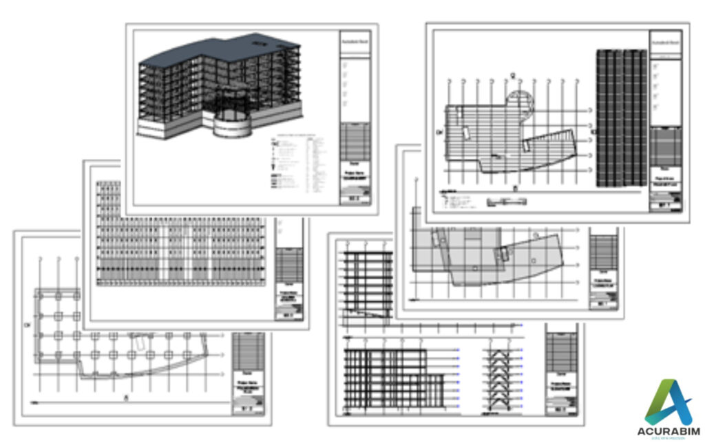
Introduction: Creating construction documents with Revit can seem like a daunting task, but with a little guidance, it’s actually quite simple. Here’s a step-by-step guide to creating construction documents with Revit: Steps For Creating Construction Documents Are As Follow: Top of Form By following these steps, you should be able to create professional-grade construction documents using Revit. With a little practice, you’ll be able to quickly and efficiently create construction documents for any project.

Creating Construction Documents with Revit A Step-by-Step Guide Read More »

Shortcuts In Revit

Introduction: As an architectural, engineering, or construction professional, you likely spend a significant amount of time working with Revit, a powerful software tool for building information modelling (BIM). To maximize your productivity and streamline your workflows, it’s essential to familiarize yourself with the various keyboard shortcuts available in Revit. These shortcuts can help you navigate the software, manipulate objects, and perform various tasks more efficiently. One of the most useful keyboard shortcuts in Revit is the “Escape” key, which allows you to cancel a command or exit a tool. This can be especially helpful if you accidentally enter a command or get stuck in a tool that you didn’t intend to use. Another essential shortcut is the “Tab” key, which allows you to toggle between open views and sheets. This can be especially useful when you’re working on multiple views or sheets at the same time and need to quickly switch between them. The “Ctrl” key is also crucial in Revit, as it allows you to perform various actions such as copying and pasting elements, creating duplicate elements, and aligning objects. For example, you can use “Ctrl + C” to copy an element, “Ctrl + V” to paste it, and “Ctrl + A” to align it with another element. The “Spacebar” is another key that can be very useful in Revit. You can use it to pan and zoom in and out of views, as well as to access various tools and commands. For example, you can press the “Spacebar” to access the “Select” tool, or hold it down to access the “Orbit” tool. There are many other keyboard shortcuts available in Revit, including ones for modifying objects, managing views and sheets, and working with text and dimensions. Some of the most useful ones include: “Escape” – cancel a command or exit a tool “Tab” – toggle between open views and sheets “Ctrl + C” – copy an element “Ctrl + V” – paste an element “Ctrl + A” – align an element with another element “Ctrl + Shift + W” – create a copy of a selected element “Ctrl + Shift + M” – mirror a selected element “Ctrl + Shift + R” – rotate a selected element “Ctrl + Shift + L” – lock a selected element “Ctrl + Shift + H” – hide a selected element “Ctrl + Shift + I” – isolate a selected element “Ctrl + Shift + E” – explode a selected element “Ctrl + Shift + J” – join two or more elements “Ctrl + Shift + T” – add text to a view “Ctrl + Shift + D” – add dimensions to a view “Spacebar” – access the “Select” tool or hold down to access the “Orbit” tool “F2” – access the “Modify” tool “F5” – access the “Properties” palette “F7” – access the “Level” tool “F8” – access the “Wall” tool It’s worth noting that some of these keyboard shortcuts may differ depending on your operating system or the version of Revit you’re using. It’s always a good idea to consult the Revit documentation or online resources to confirm the exact keyboard shortcuts for your specific setup. To maximize your productivity with Revit keyboard shortcuts, it’s essential to take the time to learn and memorize the ones that you use most frequently. You may also want to consider customizing the keyboard shortcuts to better suit your workflows and preferences. This can typically be done through the “Keyboard Shortcuts” dialog in the “Options” menu. In conclusion, keyboard shortcuts are a crucial tool for increasing your productivity and efficiency when working with Revit. By familiarizing yourself with the various shortcuts available and customizing them to suit your needs, you can significantly streamline your workflows and get more done in less time.

Shortcuts In Revit Read More »

REBAR MODELING TECHNIQUES IN REVIT2022!

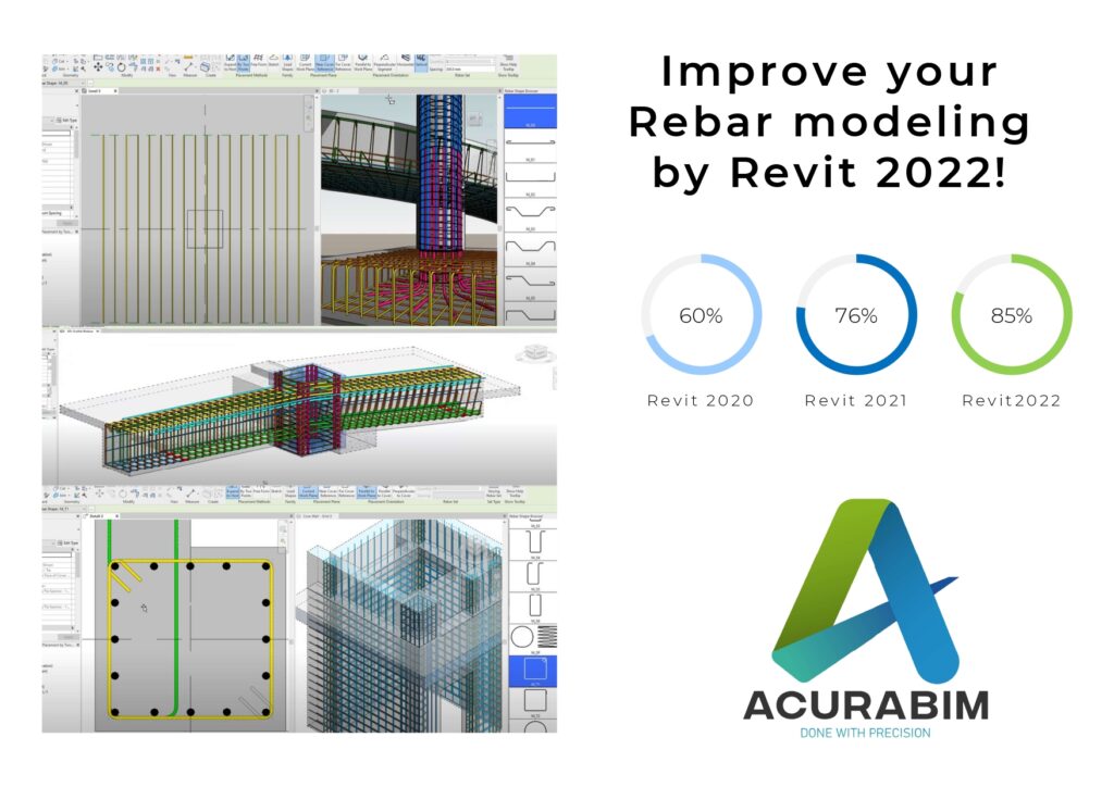
Using Two Points to Position Rebar Rebars of the correct dimensions and aligned to any project reference can be placed in Revit 2022 with only two clicks. By doing this, fewer steps are required to accurately and precisely generate bars. This capability is crucial for rebar modelling and completely transforms the way rebar detailers use Revit. This innovative technique for inserting rebar increases your productivity while modelling cast-in-place and precast reinforced concrete details in Revit. Enhancements to Rebar Performance Revit offers enhanced rebar performance in 2D views while zooming and panning during regeneration as an extra bonus for the 2022 edition. When viewing rebar in any 2D view at Fine detail, these speed benefits are apparent. Revit 2022 delivers higher rebar performance than ever before. In tests of “difficult” 2D views, the regeneration time fell from minutes to literally 3–4 seconds. Improvements to the Infrastructure In Revit 2022, Revit families made with the generic model family template can be categorised and subcategorized as Bridge and Road (e.g., Abutments, Piers, and many more). These families can define cuttable views, host rebar, be scheduled, be labelled, and so forth. Additionally, Revit 2022 offers a few minor improvements to alignment stationing: Alignment station text may include prefixes and suffixes. The genuine start and end stations of an alignment are now provided in the Revit API to aid in automating bridge design. Flip controls have been added to the alignment station label. In Revit 2022, these improvements provide better capabilities and flexibility for infrastructure workflows. Only Display Wall Core in Plan Views In earlier releases, hiding the non-core layers of walls on plan views took a lot of effort. A new option in Revit 2022 makes it simple and quick to display only the wall core layers. To display a streamlined representation of walls in your 2D views, disable the new Non-Core Layers option under Walls in the Visibility/Graphics dialogue box. Between the core bounds of the wall assembly, wall layers will still be visible. With the aid of this tool, you can quickly generate plan views in Revit that are simpler to read, increasing your productivity. 5.Move the Rebar in a Set. For structural engineers and detailers, Revit 2022 enhances rebar modelling and detailing, making the transition from separate CAD workflows to BIM simpler for you and allowing you to model and detail more quickly and correctly. While keeping the logic of the rebar set or system, you can now relocate or delete certain bars from rebar sets or area and path reinforcement systems to prevent conflicts with other rebars, openings, or other elements. Numerous sets or systems can be edited simultaneously, eliminating the requirement to divide a set into multiple sets or remove path and area reinforcement systems—workflows that were previously complex and time-consuming. This new function will greatly increase your modelling accuracy productivity and efficiency. in Revit.

REBAR MODELING TECHNIQUES IN REVIT2022! Read More »

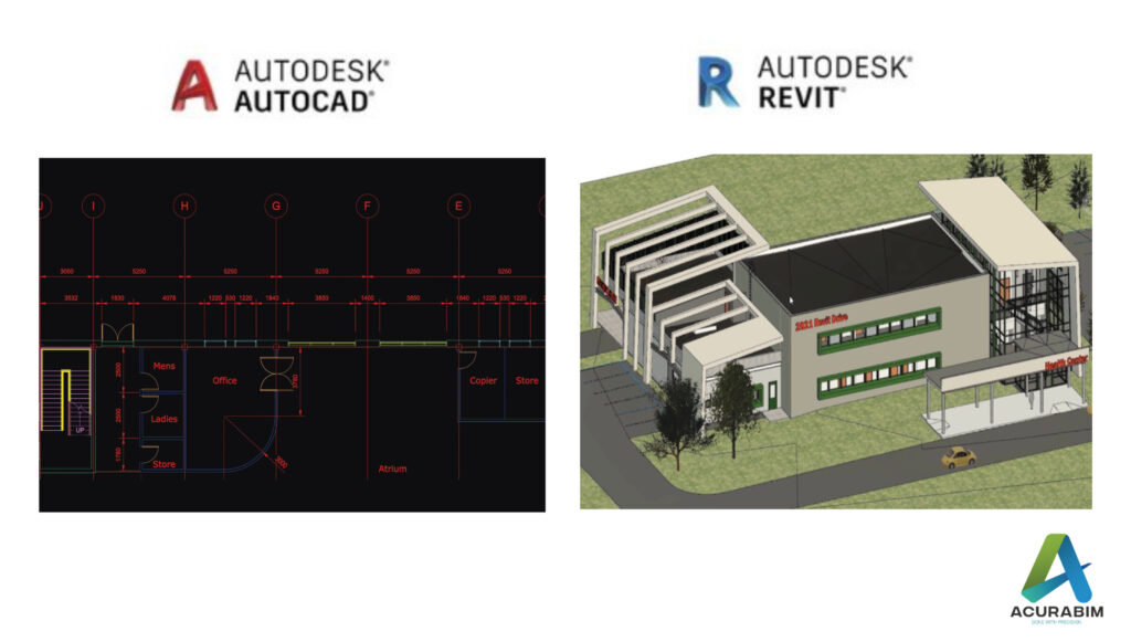
AutoCAD to Building Information Model(Revit)

Introduction: For decades, architects, engineers, and construction professionals have used Computer-Aided Design (CAD) software to create 2D drawings of building projects. However, with the rise of Building Information Modelling (BIM), many organizations are now transitioning from traditional CAD workflows to 3D modelling and collaboration. In this blog, we will explore the benefits of BIM and discuss how to make the transition from CAD to BIM as smooth as possible. Here are the steps you can follow to convert your Computer-Aided Design (CAD) data to Building Information Modelling (BIM) format: 1. Choose a BIM software: The first step in converting from CAD to BIM is to choose a BIM software that meets your needs and the needs of your organization. Some popular options include Revit, ArchiCAD, and Vector works. 2. Invest in training: It’s important to invest in training to ensure that you and your team are proficient in using the BIM software you have chosen. This can be done through online courses, workshops, or in-house training programs. 3. Clean up your CAD data: Before you begin the conversion process, it’s a good idea to clean up your CAD data to ensure that it is accurate and up-to-date. This may involve checking for errors, correcting any issues, and making sure that all relevant data is included. 4. Use conversion software: There are a number of conversion tools available that can help you import your CAD data into a BIM model. These tools can often handle a wide range of file formats, including AutoCAD, MicroStation, and others. 5. Check and verify the converted data: Once your CAD data has been converted to BIM format, it’s important to check and verify that the data has been correctly converted. This may involve comparing the converted data to the original CAD data, as well as reviewing the BIM model for accuracy and completeness. 6. Review and optimize the BIM model: Once your BIM model is complete, you should review it to ensure that it is optimized for your needs. This may involve reviewing the model for efficiency, identifying areas for improvement, and making any necessary changes. 7. Train your team: If you have a team of people working on your BIM projects, it’s important to ensure that they are trained in the use of the BIM software and the specific workflow you have established for your organization. This may involve providing additional training or creating detailed documentation and guidelines for your team. By following these steps, you can successfully convert your CAD data to BIM format and begin using BIM to design and document your building projects.

AutoCAD to Building Information Model(Revit) Read More »

Scroll to Top