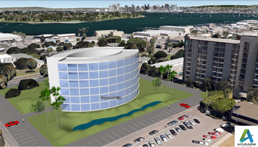
Augmented Reality in Construction Industry
What is Augmented Reality: The utilisation of information in the form of text, pictures, music, and other virtual upgrades that are combined with physical items is known as augmented reality (AR). This “real world” component is what sets augmented reality apart from virtual reality. Applications for Augmented Reality in construction: Despite being one of the largest and oldest sectors in the world, construction struggles frequently to adopt new tools. Nevertheless, innovation is a vital resource for the building sector. Another innovative development in the construction sector is augmented reality, which is a priceless tool for all facets of this sector. It makes use of cutting-edge camera and sensor technologies that blend digital components, audio, and sensory input. They all support the real-time presentation of the data. The usage of augmented reality in the construction industry is appropriate in the following application areas: Visualizing project data in real time: The incorporation of documents and digital information is Augmented Reality’s main benefit in the building industry. It makes it possible for everyone to routinely check the progress of the construction project, including workers, architects, engineers, and clients. Making measurements during construction and evaluating project effectiveness are further options. Promoting teamwork: Effective cooperation is particularly crucial in the construction industry, which relies heavily on collaboration. The best possible use of each team member is made possible with the aid of augmented reality. Problem solving and error correction can be adopted early on by continuously focusing on the desired result. The physical presence of every team member is no longer required. How augmented reality can be applied to the building industry The construction sector is slowly beginning to adopt mobile applications. Since a while ago, augmented reality wearables and construction have become increasingly popular. Through the usage of open development kits, building can be enhanced and improved at any time. Any phase of building can benefit from augmented reality: Prior to the start of construction, during the design phase. While the project is being built, AR also makes it simpler to monitor whether everything is proceeding according to plan. This makes it simple to steer clear of errors. Upon completion of the project, to confirm that all requirements have been met. AR’s advantages for the construction sector The use of augmented reality in the construction sector has many advantages. Although the expenses of this cutting-edge technology are still substantial, they are gradually declining. As a result, it is expected that small and medium-sized businesses will soon be able to invest in this method of operation. These businesses will specifically gain from the most significant benefits of augmented reality in construction during the process. Rework and downtime-related losses are reduced Project completion on schedule is particularly crucial in the construction sector to guarantee that budgets are met. BMI models have been useful, but using augmented reality in building makes this task much simpler. Construction schedules can be modified, and the logistics of the upcoming weeks can be prepared as needed, thanks to the use of both technologies. Furthermore, it’s simpler for employees to identify any overlaps. By doing so, it is unnecessary to redo any work, and virtual reality in construction encourages worker safety Enhanced project management and collaboration. Construction companies may present the outcomes even before the work is finished thanks to augmented reality. Misunderstandings are more readily discernible. Because AR Overlays assist in identifying problems more quickly, paper schedules and communication delays are also removed. Additionally, this makes it simpler to carry out inspections as needed. The collaboration between the various parties can be optimised by using apps like Assist AR or xMake. Of course, Frontline communications are no different: they all make sure that teams collaborate more effectively and accurately. The drawbacks of virtual reality in building Construction projects can be accompanied with AR for the duration of their existence. In turn, this lower building costs since accuracy rises and rework can be avoided. These benefits of augmented reality in construction unequivocally support the application of the cutting-edge technology. The available options do, however, have some restrictions. Augmented reality use in the building industry is modest. This is particularly true given that AR is still regarded as a developing technology that hasn’t undergone enough testing. The high degree of effectiveness, correctness, and consistency is debatable. But for applications in engineering and construction, these points are crucial. Complex 3D information models are currently only partially covered. The newness of this technology presents another obstacle. Many businesses are hesitant to invest in this technology since the financial ramifications are not yet fully understood. There is a learning curve that needs to be climbed before using augmented reality in building. A reliable WLAN and Internet connection must be made during the construction of an augmented reality building. The reliability of the devices is not guaranteed in a volatile environment. A look at the use of AR in construction in the future A cutting-edge technology that is expected to advance the construction sector is augmented reality. Thanks to the numerous advantages of an Augmented Reality introduction, processes can be optimised and made more efficient. As a result, future construction projects can be realised faster and safer. In fact, augmented reality engineering applications could have a huge impact on the construction sector. After all, this technology provides many opportunities for people to maximise their potential and continues to advance.
Augmented Reality in Construction Industry Read More »
