Architecture

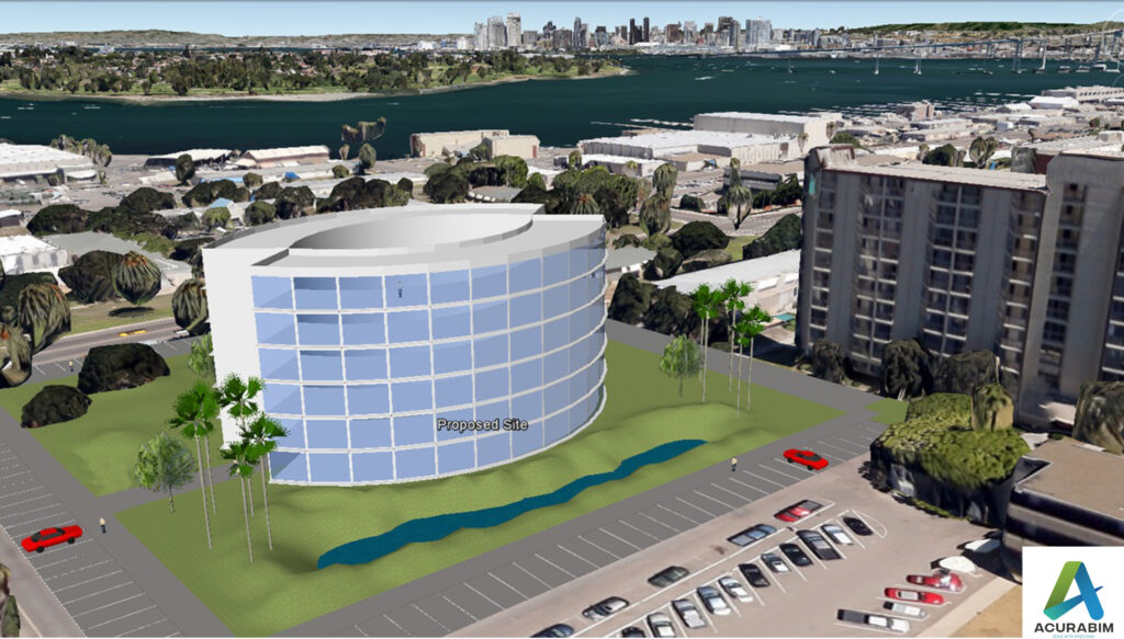
Export Sketchup file to Google Earth

Introduction: SketchUp is a powerful 3D modelling software that is widely used by architects, designers, and other professionals in the construction and design industry. One of the great features of SketchUp is the ability to export your model to Google Earth, allowing you to view your design in a real-world context. Exporting a SketchUp file to Google Earth is a simple process that can be done in just a few steps. Make sure that you have both SketchUp and Google Earth installed on your computer. Sketchup file is converted to KML file, & thus that file Is imported in Google Earth. A brief explanation for KML file is given in following para. About KML File: A KML file is a type of file that is used to store geographic data and information in a format that can be easily read by a variety of mapping and spatial analysis software. KML stands for “Keyhole Markup Language,” and it is a file format that was developed by Google for use with its Google Earth software. One of the key features of KML files is that they allow you to store and display geographic data in a way that is easily understood by both humans and computers. KML files use a system of tags and attributes to describe the data that they contain, and this makes it easy for software programs to interpret and display the data in a meaningful way. There are many different types of data that can be stored in a KML file, including points, lines, and polygons that represent features on the earth’s surface, as well as information about the appearance and behaviour of these features. For example, you can use a KML file to store information about the location and appearance of a building, or you can use it to store data about a network of roads or a set of geographic boundaries. KML files are often used in a variety of applications, including GIS software, mapping websites, and mobile apps. They are also commonly used to share geographic data with others, as KML files can be easily shared and viewed by anyone who has access to a KML-compatible application. Overall, KML files are an important tool for storing and sharing geographic data, and they are widely used in a variety of fields, including geography, mapping, and spatial analysis. Whether you are working on a professional project or simply exploring the world around you, KML files can be a valuable resource for understanding and visualizing the earth’s surface. To export your SketchUp file to Google Earth, follow these steps: Open your SketchUp model in SketchUp. Go to the “File” menu and select “Export.” In the export dialog box, select “Google Earth (KML)” as the file type. Choose a location to save the KML file, and click “Export.” Open Google Earth and go to the “File” menu. Select “Open,” and choose the KML file that you just exported from SketchUp. Your SketchUp model will now be displayed in Google Earth, allowing you to view it in the context of the real world. You can use the navigation tools in Google Earth to pan, zoom, and rotate your model, and you can also use the layers panel to turn different elements of your model on and off. Summary: Exporting a SketchUp model to Google Earth is a great way to share your design with clients and colleagues, and it can also be a helpful tool for visualizing your design in a real-world context. Whether you are working on a residential project, a commercial building, or any other type of design, exporting your SketchUp model to Google Earth can be a valuable part of your workflow.

Export Sketchup file to Google Earth Read More »
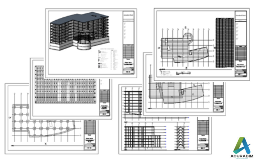
Creating Construction Documents with Revit A Step-by-Step Guide

Introduction: Creating construction documents with Revit can seem like a daunting task, but with a little guidance, it’s actually quite simple. Here’s a step-by-step guide to creating construction documents with Revit: Steps For Creating Construction Documents Are As Follow: Top of Form By following these steps, you should be able to create professional-grade construction documents using Revit. With a little practice, you’ll be able to quickly and efficiently create construction documents for any project.

Creating Construction Documents with Revit A Step-by-Step Guide Read More »

Outsourcing BIM Services

Top Advantages of Outsourcing BIM Services Digital building buy injectable testosterone cypionate online in uk in uk is the way of the future. The U.S. Architecture, Engineering, and Construction (AEC) industry’s digital revolution is being driven by (Building Information Modelling, or BIM). Recent studies predict that by 2024, the global building information modelling (BIM) market would be worth 4210 million USD. Cost and time restrictions, a lack of qualified personnel with a comprehensive grasp of BIM, and the necessary infrastructure and technology for these services are major obstacles for many businesses. It makes sense to think about outsourcing BIM services, especially the creation of Revit families and the development of Revit models, when in-house services become unsustainable. In a study of 252 general contracting companies, 45% of responding companies reported outsourcing BIM, indicating that this practice has grown to be a crucial part of BIM implementation. Still uncertain? Consider these persuasive advantages of outsourcing BIM services right now. The following are some of the top advantages of outsourcing BIM Services: Cost Savings and Risk Reduction You may increase ROI by outsourcing BIM while lowering and controlling operating expenses. Instead of spending money on an internal staff, you may employ BIM services only as needed. This makes sure that you are better prepared to scale in cases of unexpected increases in demand. You may spend less on office supplies, furniture, equipment, and employee perks by lowering operating costs. An outsourced team of highly qualified expert engineers provides you a clear view of where they are going as well as an assurance that the project is practical and doable with frequent daily meetings, online project management tools, and well-established norms. By addressing any possible red flags early on, this reduces risks. Improved Productivity   Outsourcing With the help of BIM, you may obtain services of the highest quality provided by vetted teams of experts. It enables you to concentrate on your primary strengths. You may pick from a verified worldwide talent pool through outsourcing, sometimes at cheaper rates, and it can help make up for any shortage of BIM experts in your neighbourhood. This aids you in overcoming the difficulties of completing BIM projects under pressure of time constraints, manpower constraints, and operational complexity. In order to increase production, the outsourced crew receives frequent training and supervision. Improved Interaction and Communication You may outsource with confidence if you have established workflows and the right communication tools. The ideal offshore partner may be a reliable and effective growth ally. To improve cooperation and guarantee that consumers have well-coordinated designs, offshore firms frequently adopt the most cutting-edge technologies. This saves time and effort while lowering uncertainty. A construction project’s procedure, quality, and communication requirements are all improved by outsourcing BIM and Revit drawings. Efficiency, precision, speed, and reduction are all improved. Communication and cooperation are made possible through this. Greater Speed of Turnaround Fast response times are guaranteed by outsourcing BIM component production services in several time zones. Due to the country’s particular geographic position, your offshore partner may provide 24–7 services, taking advantage of time zone variances. Additionally, a group of highly skilled engineers that have completed BIM for AV projects successfully employ cutting-edge technologies to provide short turnaround times. Additionally, accuracy and design coherence may be guaranteed by a professional quality control manager who is responsible with reviewing the development of BIM components.

Outsourcing BIM Services Read More »

Procedure of Clash Detection in Revit’s and Navisworks.

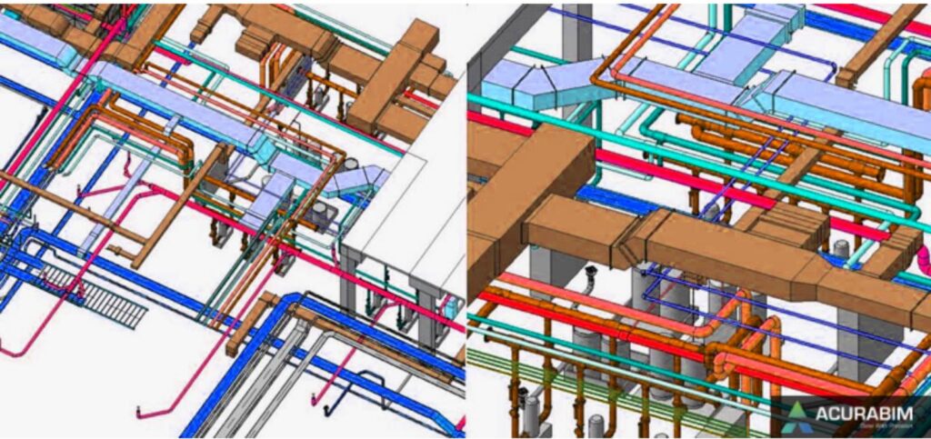
To make sure that design problems are fixed and in compliance with building standards and norms, a method called “Revit clash detection Process” checks collisions (also known as “clashes”) and interference. Both Navisworks and Revit are used for this procedure. BIM Engineers can find the clashes and certify the design without harming compliance by performing clash detection in Revit. To make sure that all the parties approve the changes and the clashes are resolved without further conflict, the resolution of the clashes is highlighted and discussed in a BIM coordination meeting with all the Design Engineers of different disciplines, the architect, engineer, contractors, and the builder. Because it can produce schedules, location-specific clashes, and other useful information, Revit Drafting Services is a great choice for validating designs through clash detection. Revit provides helpful collision detection tools, which show conflicts based on the interference of the objects and emphasise them when necessary. However, it is not particularly capable of producing reports, offering a state of clashes, creating rules, or offering tests for clearance and custom clashes, among other things. Other software can be used to carry out these operations. However, a business or team that is tackling clash detection for the first time and is still completing interference tests can move forward with Revit. Revit clash detection is sufficient even for little projects. Revit and Navisworks can both handle complex clash detection. Even though building firms and MEP contractors prefer Navisworks, clash detection in Revit offers several benefits. The following are top advantages of Procedure of Clash Detection in Revit’s and Navisworks. Reducing Wasteful Building Time By detecting collisions in the pre-construction stage, the Revit Clash Detection service reduces unnecessary construction time significantly. We may export the model to Navisworks to extract conflict reports after clash detection in Revit. Conflicts can be handled in some cases by making small adjustments and in others by holding group sessions. Whenever necessary, we may check the design and make changes. The earlier these processes are finished; the more construction time is saved after the production designs are sent to the on-site engineer. The design has not changed, and the installation is nearly complete on schedule. Reduces Construction Costs Prior to the development of BIM, managing construction costs and construction time posed serious problems. There have been instances where conflicts arose during on-site construction and had to be addressed before building could continue. Over time, design modifications were made, and it was difficult to gather all the agencies for the conference. Because of the prolonged building period and underutilization of the work force, construction firms and builders suffered significant losses. However, with the aid of BIM clash detection services, the model can be created in Revit, and any conflicts may be handled through online meetings and model sharing in a cooperative manner. Process toward Design Validation: Revit Clash detection makes it simple to handle design errors. The designs may be compared and coordinated when the 3D model is complete to see if the architectural, structural, and MEP services disciplines are in accordance with the standards and are coordinated with one another. Type of Clash Detection : Two types as stated below The number of interferences existing in a 3D model of the current design have been counted, examined, and recorded thanks to clash detection in Revit. This method is useful for assessing recently begun or completed (as constructed) projects. It significantly lowers the error-index, which lowers the project’s total productivity and length of construction. As we have a report of the BIM components or model pieces clashing with each other, we can run simple interference tests. Using connected architectural and structural models or linked MEP and structural models, these conflicts may be verified as a single file. When we do conflict detection, three different types of confrontations may be seen. There are three different types of confrontations that might occur: Hard clashes, soft clashes, and Workflow problems. Some conflicts must be disregarded and investigated on the spot. However, certain disputes must be settled before building may continue. Hard Clash Detection Method A hard clash happens when elements from two disciplines cross across. For instance, Hard collisions occur when beams and columns strike ducts, or when the ducts strike the ceiling or doors. Lack of coordination between MEP engineers or architects and structural engineers is the primary cause of serious collisions. Such conflicts may also be caused by improper modelling. Collaborative discussions, design modifications, and, in the end, modifying the BIM Models to reflect the design modifications are used to settle such conflicts. The clash detection procedure is used after remodelling. The embedded data principle is adhered to by BIM modelling software like Revit, which aims to minimise such conflicts at the modelling stage itself. Soft Clash Detection Method These conflicts happen when two disciplines don’t have enough room to move apart, causing one BIM object to overlap the other. Increasing or lowering the area available to accept the items can be used to avoid such collisions. Inference: We have seen a number of advantages of employing clash detection in Revit as well as its need. Even though Navisworks is a programme that is better suited for interference checks and reporting, Revit aids in conflict detection. Depending on the severity, the clash data may then be transferred to Navisworks for additional processing. The optimum method for conflict detection would be to start with Revit, assess the clashes, and then export the model to Navisworks. Get the reports by doing a thorough Navisworks clash detection. Have a meeting to discuss the design adjustments while reviewing the findings. Make the necessary adjustments in various disciplines based on the outcomes of the meeting to make sure the models are prepared for the extraction of the coordinated production drawings.

Procedure of Clash Detection in Revit’s and Navisworks. Read More »

Integrated Building Information Modelling

Integreated BIM Conceptual Goal This article aims to establish new integrated Building Information Modeling (BIM) trends for the building sector. Construction has somewhat adopted BIM as a cutting-edge strategy or technology to enhance project performance in the areas of productivity, efficiency, and safety. To maximise BIM, however, strategic research direction is needed to advance this technology over the whole project life cycle.   Design/Development/methodology In the context of integration within the Architecture, Engineering, and Construction (AEC) sectors, this study examines the new trends for BIM adoption.   Research results According to research, there are three phases of a project where BIM might enhance performance: pre-construction, construction, and maintenance/operation. For completion of all above design and construction cycle Autodesk introduce many excellent software’s like 2D planning done in AutoCAD and Revit, Conceptual Design and Design development and Construction Documents done in Revit, 4D Presentation, Clashes Detection,Timeline, Model Based Quantity Extraction done in Navisworks.   Innovativeness To be fully integrated with other technologies, BIM must develop. This will help projects perform better at different phases of the project life cycle.

Integrated Building Information Modelling Read More »

Scroll to Top