Author name: Acura

AutoCAD to Building Information Model(Revit)

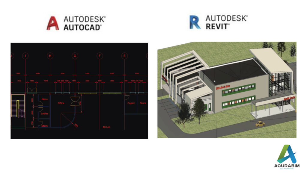
Introduction: For decades, architects, engineers, and construction professionals have used Computer-Aided Design (CAD) software to create 2D drawings of building projects. However, with the rise of Building Information Modelling (BIM), many organizations are now transitioning from traditional CAD workflows to 3D modelling and collaboration. In this blog, we will explore the benefits of BIM and discuss how to make the transition from CAD to BIM as smooth as possible. Here are the steps you can follow to convert your Computer-Aided Design (CAD) data to Building Information Modelling (BIM) format: 1. Choose a BIM software: The first step in converting from CAD to BIM is to choose a BIM software that meets your needs and the needs of your organization. Some popular options include Revit, ArchiCAD, and Vector works. 2. Invest in training: It’s important to invest in training to ensure that you and your team are proficient in using the BIM software you have chosen. This can be done through online courses, workshops, or in-house training programs. 3. Clean up your CAD data: Before you begin the conversion process, it’s a good idea to clean up your CAD data to ensure that it is accurate and up-to-date. This may involve checking for errors, correcting any issues, and making sure that all relevant data is included. 4. Use conversion software: There are a number of conversion tools available that can help you import your CAD data into a BIM model. These tools can often handle a wide range of file formats, including AutoCAD, MicroStation, and others. 5. Check and verify the converted data: Once your CAD data has been converted to BIM format, it’s important to check and verify that the data has been correctly converted. This may involve comparing the converted data to the original CAD data, as well as reviewing the BIM model for accuracy and completeness. 6. Review and optimize the BIM model: Once your BIM model is complete, you should review it to ensure that it is optimized for your needs. This may involve reviewing the model for efficiency, identifying areas for improvement, and making any necessary changes. 7. Train your team: If you have a team of people working on your BIM projects, it’s important to ensure that they are trained in the use of the BIM software and the specific workflow you have established for your organization. This may involve providing additional training or creating detailed documentation and guidelines for your team. By following these steps, you can successfully convert your CAD data to BIM format and begin using BIM to design and document your building projects.

AutoCAD to Building Information Model(Revit) Read More »

Collaborating in Revit

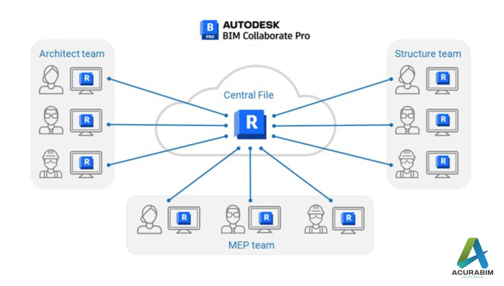
Introduction: Building Information Modelling (BIM) has revolutionized the way that architects, engineers, and construction professionals design and document building projects. One of the key tools used in BIM is Revit, which allows teams to create 3D models of buildings and their components and collaborate in real-time. However, collaborating with Revit requires careful planning and effective communication to ensure that everyone is working towards a common goal. In this blog, we will explore best practices for collaborating with Revit and discuss strategies for managing changes and resolving conflicts. 1. Setting up a Revit collaboration workflow: Before you start working with Revit, it’s important to establish a clear workflow for collaboration. This should include: • Defining roles and responsibilities: Each team member should have a clear understanding of their role and responsibilities within the project. For example, one team member may be responsible for creating the initial Revit model, while another may be responsible for updating the model as changes are made. • Establishing a central file server: All Revit files should be stored on a central file server that can be accessed by all team members. This will help to ensure that everyone is working with the most up-to-date version of the model. • Creating a shared project calendar: A shared project calendar can help team members to coordinate their work and stay on track. This can be as simple as an Excel spreadsheet or a more sophisticated project management tool like Asana or Trello. 2. Managing changes and resolving conflicts: As the Revit model evolves, it’s likely that changes will be made by different team members at different times. It’s important to have a system in place for managing these changes and resolving conflicts that may arise. Here are a few tips: • Use Revit’s version control features: Revit includes a range of version control features that allow you to track and manage changes to the model. For example, you can use the “Compare” tool to see the differences between two versions of the model, or use the “Worksets” feature to allow multiple team members to work on different parts of the model simultaneously. • Communicate clearly and regularly: good communication is key to successful collaboration. Make sure to have regular check-ins with your team and be clear about any changes or updates you make to the model. • Use conflict resolution tools: If conflicts do arise, there are a number of tools that can help you resolve them. For example, you can use the “Audit” tool in Revit to identify and fix any errors in the model, or use the “Revision Cloud” feature to highlight areas of the model that need attention. Conclusion: Collaborating with Revit can be a challenging but rewarding experience. By setting up a clear workflow and using the tools and features available in Revit, you can ensure that your team is working efficiently and effectively towards a common goal. With careful planning and good communication, you can successfully navigate the complexities of BIM and deliver high-quality building projects.

Collaborating in Revit Read More »

Family Creation In Revit

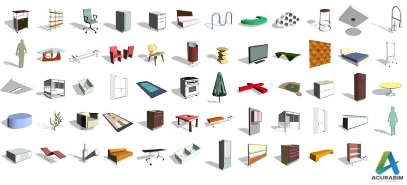
Family Creation In Revit: Creating families in Autodesk Revit can be a powerful tool for adding customized elements to your building design projects. Families are essentially pre-made objects that can be inserted into your Revit model and behave just like any other element, such as walls or doors. The main advantage of using families is that they allow you to quickly add complex or unique objects to your model without having to manually draw them each time. In this blog, we’ll cover the basics of creating families in Revit, including an overview of the different types of families, the steps involved in creating a family, and some tips and best practices to follow. Types of Families in Revit Before diving into the creation process, it’s important to understand the different types of families that are available in Revit. There are three main types of families: System families: These are the basic building blocks of your Revit model, such as walls, floors, roofs, and ceilings. System families are pre-made and cannot be edited or modified. Loadable families: These are pre-made families that can be inserted into your model from the Revit library or from a file on your computer. Loadable families can be modified to some extent, but they cannot be created from scratch. In-place families: These are families that are created directly in your Revit model, rather than being inserted from a library or file. In-place families are completely customizable and can be created to meet your specific needs. Creating a Family in Revit To create a new family in Revit, follow these steps: In the Revit ribbon, go to the “Create” tab and click on the “Family” button. This will open the “New Family” dialog box. In the “New Family” dialog box, choose the type of family you want to create. You can choose between three types: Generic Model, Generic Annotation, or Loadable Annotation. Select the appropriate template for your family. If you’re creating a generic model family, you’ll have the option to choose between several different templates, such as walls, floors, or windows. If you’re creating a generic annotation family, you’ll have the option to choose between text, dimensions, or symbols. Click “OK” to create the new family. This will open the “Family Editor” window, which is where you’ll create and customize your family. In the “Family Editor” window, use the various tools and features to create your family. This may involve drawing lines, arcs, and circles, as well as using various constraints and parameters to define the behaviour of your family. Tips and Best Practices for Creating Families in Revit Here are a few tips and best practices to keep in mind when creating families in Revit: Start simple: It’s often best to start with a simple family and gradually add more complexity as you become more comfortable with the family creation process. This will help you avoid becoming overwhelmed and will make it easier to troubleshoot any issues that arise. Use good modelling practices: When creating your family, be sure to follow good modelling practices, such as using consistent and logical naming conventions, keeping your model organized and easy to understand, and avoiding unnecessary geometry. Test your family: Before you finish your family, be sure to test it in a Revit project to ensure that it behaves as intended. This will help you identify any issues or bugs that need to be addressed. Save and backup your family: As with any important project, be sure to save your family regularly and create backups

Family Creation In Revit Read More »

Scan To BIM in Revit

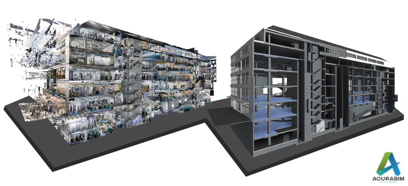
Scan To BIM in Revit: Scan to BIM (Building Information Modelling) is a process of creating a digital 3D model of a physical building or structure using point cloud data obtained from laser scanners or other digital imaging technologies. This process allows architects, engineers, and construction professionals to create accurate, detailed, and up-to-date models of existing structures, which can be used for various purposes such as renovation, retrofitting, and facility management. Here are some pointers on how to perform Scan to BIM in Revit:  Obtain point cloud data: The first step in the Scan to BIM process is to obtain accurate point cloud data of the physical building or structure. This can be done using laser scanners, photogrammetry, or other digital imaging technologies. Clean and organize the point cloud data: Once you have the point cloud data, it is important to clean and organize it to ensure that it is ready for use in Revit. This may involve removing excess data, aligning the point cloud with a known coordinate system, and organizing the data into logical groups or layers. Import the point cloud data into Revit: Once the point cloud data is organized, it can be imported into Revit using the “Import Point Cloud” tool. This tool allows you to select the point cloud file and specify the coordinate system, scaling, and other relevant parameters. Create a 3D model from the point cloud data: Once the point cloud data is imported into Revit, you can use it to create a 3D model of the physical building or structure. This can be done by selecting points or groups of points from the point cloud and creating 3D elements such as walls, floors, roofs, and so on. Add annotations and details to the model: As you create the 3D model, you can also add annotations and details such as dimensions, notes, and materials to provide more information about the building or structure. Use the 3D model for various purposes: Once the 3D model is complete, it can be used for various purposes such as renovation, retrofitting, facility management, and more. You can also use the model to generate 2D construction documents, create visualizations and animations, and perform structural and MEP analysis. In summary, Scan to BIM in Revit involves obtaining point cloud data of a physical building or structure, importing the data into Revit, creating a 3D model from the data, adding annotations and details to the model, and using the model for various purposes. By following these steps, you can create accurate and detailed digital models of existing structures, which can be used for a wide range of purposes in the architecture, engineering, and construction industries. Application of Scan to BIM: As-built documentation: Scan to BIM can be used to create an accurate, digital representation of an existing building, which can be used for as-built documentation and record-keeping purposes. Renovations and retrofits: Scan to BIM can be used to create a detailed model of an existing building, which can be used to plan and execute renovations or retrofits. Facility management: A BIM model created using Scan to BIM can be used to manage and maintain a building over time, including tasks such as tracking equipment, scheduling maintenance, and identifying potential issues. Energy analysis: A BIM model created using Scan to BIM can be used to analyse a building’s energy performance and identify opportunities for energy efficiency improvements. Coordination: A BIM model created using Scan to BIM can be used to coordinate the design and construction of a project, ensuring that all stakeholders have access to the same accurate, up-to-date information about the project.

Scan To BIM in Revit Read More »

Level of Detail/Development in Revit Modelling

Level of Detail/Development in Revit Modelling: The Level of Detail/Development (LOD) describes the overall condition of your information model at a specific stage of the design process. This contains the accompanying data as well as the graphical elements themselves. Your model should go from a very rough concept to the as-builts and record drawings over time. According to the AIA E202 contract agreement, this procedure has been standardized into five separate categories. Model Advancement: The idea of model progression lies at the heart of the five-layer LOD. It is critical to understand that not all elements will advance through the model at the same rate or be present at every level. For instance, while essential structural elements may advance through all 5 levels, fittings on mechanical systems could not exist until level 400. Additionally, different disciplines will move through the procedure at various speeds. Structure steel frequently reaches the 400 level before all mechanical has achieved the 300 level. This must be understood by the entire team, who must then create plans to prevent items from reaching the field if their final design will be impacted by model elements that have not yet been established. For instance, steel cannot be released from the 300 level until mechanical loads have been determined. This is just to ensure that the loads required to calculate the steel are accurate. It does not imply that mechanical must be finished to the same degree. Ownership of graphical objects and the data they are connected with may change as the model develops from conceptual to as-built. The changeover from one data format to another may also be a part of this. It is crucial that during this procedure, data accuracy be upheld. Simplifying LOD: At various stages of a project’s development cycle, it is crucial to have a clear description of what is contained in the information model. One of the most crucial components of a BIM-based project’s success is the understanding of expectations, roles, and duties. In order to help with this, GSA has created a number of resources. Please refer to following list to know about the model’s usable features at each stage of development (e.g., level 400 models may be used for exact pricing) LOD 100 (Conceptual) There may not be many brownfield projects that include LOD 100 because it is the beginning of a project. The conceptual design phase of a typical project is fairly comparable to LOD 100. A model will be at its most basic during this stage. A basic site layout may be present, the building will be located, and some very rudimentary evaluations may be carried out. These assessments could involve preliminary whole-site construction phasing, conceptual cost based on cost per square foot, and whole-building energy analysis. There might not always be any model data available for LOD 100. Only analytical data, 2D CAD data, or even hand drawings could be included. When compared to LOD 200 and beyond, LOD 100 is frequently completed by GSA staff or a separate architect. Any model data should, wherever feasible, be developed with the knowledge that it will eventually need to be transferred to a BIM design tool. For instance, if Revit will be used to finish the future designs (200 and 300), a tool that is compatible with Revit should be taken into account for the 100-level massing, modelling, and analysis. LOD 200 (Approximate Geometry) Schematic design and design development are comparable to LOD 200. The conceptual massing model and related data will be transformed during this phase into a model suited for the preparation of construction documents. Given that it includes both the conventional schematic design and design development activities, this is one of the phases that any model will go through that is the longest. By the end of this 200-level course, a model including the approximate number, size, position, and systematic relationships of the majority of the deployed items will exist. Basic information will be initially put in for all object’s data. Even if precise item information might not yet be accessible, space claims for each object or system should at the very least be taken into consideration. During this phase, preliminary high-level coordination should be taking place. Planning should be the main emphasis of coordination, not violent conflicts (e.g., vertical space allotment for utilities not pipe-on-pipe collisions). According to the project’s BEP, this coordination should be cross-disciplinary and conducted at project coordination meetings. LOD 300 (Precise Geometry) LOD 300, the stage where a design starts to precisely resemble what will be built, is comparable to construction papers. The geometry of specific pieces is verified to be 3D. Dimensions, capabilities, and relationships of the object are specified. Upon completion of level 300, a model with the precise number, size, placement, and logical relationships of every object that will eventually be placed will be available. All necessary fundamental data will be entered into the data about all items. There shouldn’t be any rough forms or space demands for any installed object (space claims to protect space for code compliance or similar will still be present). Throughout this phase, individual object level cooperation should be occurring. Major harsh conflicts should be the focus of coordination (e.g., pipe-on-pipe collisions). In this time, the AE and Constructors ought to be present at the coordination sessions. LOD 400 (Precise Geometry) When manufacturing and assembly can be driven directly from the model, LOD 400 is attained. The level 400 information model is produced exclusively by the trade partners with input from the AE for the majority of item types. The design information model frequently becomes inactive at this stage of development while fabrication models are derived from them on a different CAD platform. For design or as-built models, different tools are needed than for manufacturing level models. Trade scheduling is one of LOD 400’s main differences. At levels 100 through 300, various trades are finishing the stages at various times. For instance, the crafts of architectural components, structural steel and foundations, and

Level of Detail/Development in Revit Modelling Read More »

Scroll to Top